
Analysis and control of the causes of cracking of high-speed steel rolls
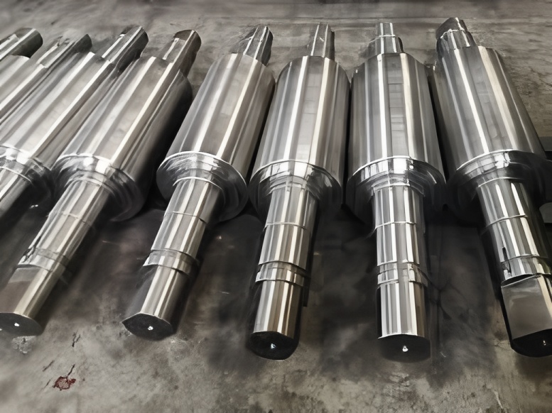
High-speed steel (HSS) rolls have become a core roll material for bar, wire rod, and section mills due to their excellent wear resistance and ability to maintain roll surface roughness over long campaigns. However, many mills still face premature cracking, groove explosions, and wedge failures when switching from traditional high-chromium cast iron or infinitely chilled ductile iron rolls to high-speed steel rolls. This article systematically analyses the cracking mechanisms of high-speed steel work rolls and presents practical control measures based on industrial experience with HANI high-speed steel rolls in bar mills.
The content is intended for rolling mill engineers, roll shop specialists, and mill roll manufacturers who require actionable guidance to improve roll life, reduce unplanned stoppages, and optimize rolling mill roll material utilization.
Primary long-tail focus keywords (selective usage): high-speed steel rolls, rolling mill rolls, steel mill work rolls, forged and cast rolls, tungsten carbide composite rolls
1. Application background of high-speed steel rolls in bar mills
A bar factory operates four continuous bar production lines with a combined annual capacity of approximately 2.7 million tons. The product mix includes:
- Construction rebar
- Mining anchor steel
- Prestressed precision-rolled thread bars
Since 2010, the finishing stands have gradually replaced high-chromium cast iron rolls and infinitely chilled ductile iron rolls with HANI high-carbon, high-vanadium series high-speed steel rolls. Industrial statistics from these rolling lines indicate:
- Single-groove steel throughput increased by 5–6 times compared with the previous roll materials.
- Roll surface roughness is maintained for significantly longer campaigns, improving bar surface finish.
- Dimensional accuracy of rolled products is markedly improved due to reduced wear and stable groove geometry.
- Reduction in roll changes and improved production efficiency of the rolling mill.
However, under the original rolling conditions suitable for high-chromium cast iron rolls, the high-speed steel rolls experienced frequent failures in the finishing group grooves, especially:
- K1 finished groove: cross rib (thread rib) separation and detachment at the groove bottom.
- K3/K4 slit and pre-slit grooves: inter-groove cracking and wedge (splitter) fractures.
These groove explosions and wedge failures led to:
- Unscheduled mill stops and accelerated roll changes.
- Reduced steel qualification rate and increased cobbles and misrolls.
- Higher maintenance workload in the roll shop and higher grinding costs.
To overcome these problems, the mill systematically optimized rolling conditions, cooling systems, and groove design parameters in line with the characteristics of HANI high-speed steel rolls.
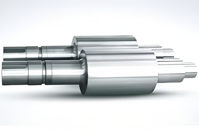
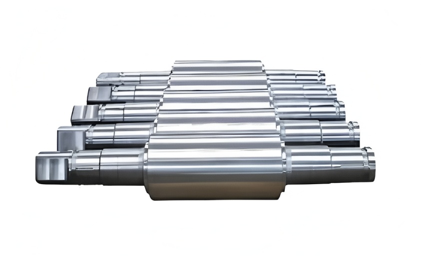
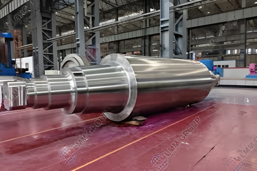
2. Material characteristics of high-speed steel rolls
High-speed steel rolls used in hot bar finishing stands are typically high alloy, high carbon, wear-resistant tool steel type materials treated by casting and special heat treatment. The main material characteristics of HANI high-speed steel rolls can be summarized as follows:
- Carbon content: approximately 1.5–2.0%
- Total alloy content: generally >15% (Cr–Mo–V–W system, exact composition adjusted according to stand and application)
- Microstructure: fine tempered martensite matrix with a high volume fraction of hard carbides (MC, M6C, etc.)
- Hardness: typically 70–80 HSD in the working layer (depending on specification and manufacturer)
- Wear resistance: significantly higher than high-chromium cast iron and ICDP rolls
- Thermal expansion coefficient: relatively high, leading to higher thermal stress sensitivity
- Toughness / impact resistance: lower than forged rolls and some cast iron grades, requiring careful control of mechanical shocks
These characteristics explain why high-speed steel rolls can deliver outstanding wear life, but are more prone to thermal fatigue cracking and mechanical cracking if cooling and rolling parameters are not adapted accordingly.
3. Working conditions of high-speed steel work rolls
In hot rolling of bars, the finishing group work rolls (often 4–6 stands in a continuous bar mill) are subjected to a combination of harsh operating conditions:
- High contact temperature: rolled stock typically enters finishing stands at 950–1050 °C.
- Rapid temperature cycling: roll surfaces heat up when in contact with bar and then rapidly cool by spray water between passes.
- High rolling speed: in modern high-speed bar mills, finishing speed can reach 12–20 m/s or higher.
- Mechanical loads: large rolling forces, torque, bending and fluctuating impact loads caused by bite, bar head, tail, and cobbles.
- Friction and sliding: in addition to pure rolling, local slip occurs especially during threading, bar misalignment, and shape rolling.
- Roll pass design: ribbed bars, slit rolling, and pre-slit passes create complex groove geometries with local stress concentration.
Therefore, cracking of high-speed steel rolls is not caused by a single factor, but by the combined effect of thermal fatigue stress, mechanical stress, and frictional stress. Understanding these mechanisms is the premise for optimizing cooling, process parameters, and roll pass design.
4. Analysis of cracking causes in high-speed steel rolls
4.1 Thermal fatigue stress cracking
During operation, the roll surface is repeatedly heated and cooled:
- Heating stage: the bar with a temperature near 1000 °C contacts the roll groove, rapidly heating the surface layer of the roll.
- Cooling stage: after the bar leaves, high-pressure cooling water sprays directly onto the hot groove surface, rapidly cooling it down.
This process creates large temperature gradients along both the surface and depth of the roll, producing cyclic thermal stresses. Over time, these stresses lead to:
- Radial thermal fatigue stress accumulation around the roll grooves.
- Micro-cracks initiation at microstructural weak points such as carbide-matrix interfaces and grain boundaries.
- Crack propagation along carbide-matrix boundaries, especially in high alloy structures with high hardness and high thermal expansion coefficient.
Under abnormal conditions, thermal stress levels sharply increase:
- Bar jamming or stop in stand leads to local overheating of the groove surface.
- Cooling water interruption or nozzle blockage causes uneven cooling and local hot spots.
- Extreme water quenching of a locally overheated groove area leads to severe thermal shock.
When the local thermal stress exceeds the strength limit of the high-speed steel, vertical cracks form, typically along crystalline boundaries or carbides. For HANI rolls with about 1.5–2.0% C and >15% alloy content, the combination of:
- High hardness
- High thermal expansion coefficient
- Relatively lower toughness compared with forged steel
makes the material more sensitive to thermal fatigue. The groove bottom transverse ribs of K1 (ribbed bar groove) and the groove spacers of slit grooves are typical locations where stress concentration occurs, resulting in groove explosion when crack propagation reaches a critical level.
4.2 Mechanical and frictional stress cracking
In addition to thermal fatigue, the roll is also subjected to complex mechanical stresses and frictional forces:
Main mechanical stresses include:
- Direct compressive and shear stresses induced by rolling load in the contact zone.
- Bending stresses from roll separating force and pass line condition.
- Torsional shear stress resulting from drive torque transmission.
Additional frictional and impact loads come from:
- Relative sliding between stock and roll during threading and unstable rolling.
- Impact of bar head and tail when entering and leaving the stand.
- Cobbles and misalignment producing very high local impact load.
- Flying shear defects such as “blackhead steel” (insufficiently cut ends) causing heavy impact in the first downstream stand.
- Low temperature rolling on the edges or rolling of hard inclusions and foreign matter (e.g. scrap pieces, scale lumps).
Although high-speed steel rolls have excellent hardness and wear resistance, their impact toughness is lower than that of forged steel rolls or some ductile iron rolls. Once mechanical stress cracks appear and grow, they can easily trigger catastrophic groove explosion accidents. Field observations show:
- Mechanical stress cracks often appear as oblique cracks with no fixed distribution pattern.
- Cracks usually propagate against the rolling direction.
- Expansion speed is very fast and difficult to control once initiated.
Effective control must therefore address both thermal and mechanical aspects of the roll operating environment.
5. Cooling water management and roll cracking control
For high-speed steel work rolls, the design, quality, and regulation of cooling water are decisive for controlling thermal fatigue. HANI implemented a comprehensive water management system, greatly reducing cracking frequency.
5.1 Cooling water quality control
Mill cooling water circulates in an open environment and is easily contaminated by scale, dust, lubricants, and oil leakage. Deteriorated water quality can lead to:
- Scale deposits on roll surfaces and inside nozzles.
- Nozzle blockage leading to local overheat of grooves.
- Reduced cooling efficiency and uneven temperature distribution.
- Corrosion of cooling water pipelines and roll chock housings.
To maintain stable and clean cooling water for rolling mill rolls and backup rolls, HANI added:
- High-efficiency inclined-plate chemical oil removers
- Sludge filter presses
- Improved chemical sedimentation units
The water treatment process is arranged as follows:
- Return water channel: hot and dirty cooling water flows through iron sheet ditches to remove coarse solids.
- Primary swirl sedimentation tank: coarse particles and heavy scale settle out.
- Chemical degreasing unit: chemicals are added to promote oil separation and flocculation, followed by settling and oil skimming.
- pH adjustment: neutralization agents are added to keep water within the specified pH range.
- Hot well and pump station: clarified water is collected and pumped to cooling towers.
- Cooling towers: water temperature is reduced, then distributed to cold wells and finally returned to the rolling mill spray headers.
The target water quality parameters for rolling mill roll cooling are summarized in the following table:
| Parameter | Unit | Control value | Parameter | Unit | Control value |
|---|---|---|---|---|---|
| pH | – | 7 – 9 | Total iron | mg/L | ≤ 1.0 |
| Turbidity | NTU | < 30 | Oil content | mg/L | ≤ 5 |
| Total hardness | mg/L (as CaCO₃) | < 500 | Conductivity | µS/cm | < 1500 |
| Chloride | mg/L (Cl⁻) | ≤ 400 | Bacterial count | count/mL | < 1.0 × 10⁵ |
Keeping these indicators within range ensures stable heat transfer, minimal scaling, and consistent cooling of high-speed steel rolls and backup rolls, which is a prerequisite for minimizing thermal cracking.
5.2 Cooling water pressure and flow rate
In addition to water quality, the water quantity and pressure at the roll surface greatly influence thermal stress. For the bar mill in question, the following parameters are adopted:
- Cooling water pressure: maintained between 0.4–0.6 MPa.
- Single groove water flow for Φ10–Φ50 mm bars: typically 300–500 L/min.
Nozzle size and quantity are selected based on billet size, groove size, stand speed, and pass schedule. Seasonal and ambient temperature variations also require dynamic adjustment:
- In summer, higher ambient temperature and higher bar temperature may require slightly increased water volume while avoiding over-cooling.
- In winter, especially in northern regions with ambient temperatures below −10 °C, excessive water cooling can cause thermal shock and cold cracking, requiring careful control.
For cold start or long downtime start-up, the mill applies a gradual temperature rise strategy:
- Limit steel passing frequency in the first heats.
- Monitor temperature difference between groove surface and ambient.
Operational tests have shown that the temperature difference between the groove surface and ambient should be maintained within about 15 °C when the mill is in stable operation to effectively reduce thermal fatigue crack initiation.
5.3 Innovative groove cooling design
Traditional cooling of rolling mill rollers often uses single-point nozzles positioned at the entry and exit sides of both upper and lower rolls. This arrangement can suffer from:
- Random nozzle diameters and angles, causing uneven cooling.
- Insufficient cooling in the middle sections of grooves.
- Excessive cooling or direct water impact on entry guides, leading to “blackhead steel”.
To provide more uniform and controlled cooling for high-speed steel rolls, HANI developed annular combined spray devices for different pass schedules:
- Spray rings are fabricated from stainless steel to resist corrosion.
- Spray curtain width is designed to be 2–4 cm wider than the groove width to ensure full coverage.
- Nozzle jets are oriented at about 30° tangential angles to the roll surface to minimize direct impact and thermal shock.
- Exit side cooling accounts for about 70% of the total water volume, intensively cooling the groove immediately after bar separation.
- Nozzles are arranged to avoid direct impingement on entry guides, reducing the risk of blackhead steel due to chilling of bar ends.
- Main nozzles near the exit guide supply about 30% of total water flow, ensuring rapid heat removal from the highest temperature region.
- Compared with upper rolls, lower rolls receive 10–15% more cooling water because their natural convection and heat dissipation conditions are poorer.
This optimized cooling concept ensures a more uniform temperature field on the roll barrel, reduces thermal gradients between upper and lower grooves, and significantly mitigates initiation of thermal fatigue cracks.
6. Groove and pass design optimization for high-speed steel rolls
Introducing high-speed steel rolls into existing mills without adapting the roll pass design often results in higher failure rates. Based on operational experience, HANI optimized several key groove parameters for K1–K4 passes.
6.1 Increasing inter-groove center distance and fillet radii
Insufficient center distance between adjacent grooves produces higher stress concentration at groove spacer rings. Under combined thermal and mechanical loading, this can promote inter-groove cracking and wedge breakage.
For different rebar diameters, HANI adjusted the groove center distance and fillet radii as follows:
| Rebar diameter | Previous center distance | Optimized center distance | Notch fillet radius |
|---|---|---|---|
| Φ10–Φ14 mm | 10 mm | 15 mm | Increased from 0.8 mm to 1.2 mm |
| Φ16–Φ25 mm | 15 mm | 20 mm | Increased from 0.8 mm to 1.2 mm |
| > Φ25 mm | ≤20 mm (typ.) | 25 mm | Increased from 0.8 mm to 1.2 mm |
Increasing the center distance reduces the overlap of stress fields from adjacent grooves, while larger fillet radii help reduce local stress concentration at notch corners. For high-speed steel rolls with lower toughness, this design adaptation significantly reduces inter-groove cracking.
6.2 Optimization of K3/K4 slit wedge geometry
In slit rolling technology, K3 pre-slit grooves and K4 cutting or final slit grooves are equipped with wedge-shaped partitions (cutting wedges). These wedges must:
- Maintain sufficient sharpness to slit the bar effectively.
- Have enough cross-section and radius to avoid excessive stress concentration and wear.
Based on extensive trials, HANI adopted the following wedge tip arc radii:
- K3 pre-slit wedge tip: arc radius 1.4–2.0 mm
- K4 cutting pass wedge tip: arc radius 0.6–0.9 mm
The design aims to maximize the allowable wedge radius while still meeting the cutting and shape-forming requirements. This balances:
- High wear resistance of the wedge tip (important for high throughput of slit passes).
- Adequate toughness to prevent wedge tip chipping or catastrophic fracture.
6.3 Control of K2 width-to-groove diameter ratio
The K2 pass usually acts as an intermediate groove before the finishing K1 ribbed groove. Excessive K2 bar width relative to groove diameter can lead to:
- Overly large reduction in K1, causing intense metal flow in the ribbed groove.
- Repeated rubbing of the bar against the same groove region.
- Formation of filamentous metal loss or periodic block loss from the groove ribs.
To avoid these phenomena, the following design rule is applied:
K2 bar width to inner groove diameter ratio should be maintained below 1.7.
This restriction ensures a reasonable distribution of reduction across passes and contributes to stable groove wear and reduced groove explosion risk in the K1 finishing pass.
7. Process discipline and roll shop practices
Even with optimized water systems and groove design, maintaining strict process discipline and good roll shop practices is crucial for preventing cracking in high-speed steel rolls.
7.1 Control of single-groove steel throughput
Excessive steel tonnage rolled through a single groove without adequate inspection or grinding increases the probability of thermal fatigue crack accumulation. HANI recommends the following throughput limits for high-speed steel rolls:
| Groove / pass | Function | Recommended throughput |
|---|---|---|
| K1 ribbed groove | Finished rebar groove | Approx. 400–450 t per groove |
| K4 pre-slit groove | Pre-slit / slit rolling pass | Approx. 2000–2500 t per groove |
These values should be adjusted according to steel grade, rolling schedule, speed, and specific roll grade, but the concept of controlled groove tonnage and timely inspection is universal.
7.2 Roll grinding and crack removal
When high-speed steel rolls are returned to the roll shop, the following principles are applied during roll grinding and maintenance:
- All visible edge and bottom cracks in the groove must be completely removed.
- Notches and ribs should be carefully checked; no micro-cracks, shelling, or surface defects are allowed.
- Grinding parameters (wheel type, feed, speed) should be chosen to minimize grinding burns and new crack initiation.
- Dressing and inspection frequency should be higher than for conventional cast iron rolls, reflecting the higher value of HSS rolls.
Proper mill roll grinding procedures are an important supplement to process control and directly influence the usable life of expensive high-speed steel work rolls.
7.3 Guide installation, cooling control, and cobble handling
Process discipline at the mill stand includes:
- Entry and exit guides must be installed so that no metallic contact occurs between guides and roll groove surfaces.
- Entry-side cooling water should be controlled to avoid over-chilling the bar ends, which can cause blackhead steel and mechanical impact on rolls.
- Operators must closely monitor for wrapping (bar sticking around the roll). In a wrapping incident, cooling should be maintained until the scrap bar temperature drops near ambient before stopping water and removing the scrap. This avoids severe thermal shock and micro-crack development.
- Regular inspection of flying shear cutting quality to avoid blackhead steel entering the finishing stands.
These measures, although operational, are closely related to the long-term integrity of high-speed steel rolls and their resistance to spalling and cracking.
8. Backup roll considerations and interaction with work rolls
In tandem and multi-stand mills, not only the work rolls but also the backup rolls (where used) are subjected to combined thermal, mechanical, and frictional stresses. Although backup rolls normally operate at lower surface temperature and wear, their performance affects:
- Work roll bending and contact pressure distribution
- Strip or bar shape control
- Line vibration and chatter, which can induce cyclic stress fluctuation in work rolls
Proper backup roll material selection (forged steel, enhanced cast iron, forged and cast composite rolls, etc.), correct backup roll grinding, and regular inspection of backup roll bearings and chocks contribute indirectly to reducing the stress level on high-speed steel work rolls.
In bar mills using primarily work rolls without traditional backup rolls, similar considerations apply to roll necks, chocks, bearings, and the roll stand rigidity to avoid excessive bending and misalignment that can localize stress in the grooves.
9. Results of comprehensive cracking control measures
After implementing the above measures — including water quality improvement, cooling system redesign, groove optimization, process discipline enhancement, and roll shop procedure upgrades — the bar factory using HANI high-speed steel rolls recorded the following changes:
- Cracking incidents of high-speed steel rolls were reduced from 4–5 cases per month to less than one case per month.
- Unexpected groove explosions and wedge fractures were largely eliminated.
- Average single-groove throughput was increased and stabilized, fully exploiting the wear resistance of high-speed steel.
- Roll consumption per ton of steel decreased, reducing operating costs.
- Product surface quality improved due to more stable roll surface roughness and minimized repair grinding defects.
- Production efficiency and on-time delivery improved because of fewer unplanned roll changes and cobbles.
This demonstrates that high-speed steel rolls can deliver their full potential only when the rolling mill systematically adapts its water management, pass design, and process discipline to the characteristics of the material.
10. Practical recommendations for mills using high-speed steel rolls
For rolling mills planning to adopt or optimize high-speed steel rolls, the following practical recommendations are suggested as a reference:
- Evaluate current cooling system: measure water pressure, flow rates per groove, and temperature distribution; check nozzle layout and clogging tendency.
- Upgrade water treatment: ensure pH, hardness, oil content, turbidity, and total iron meet control values suitable for high-speed steel rolls.
- Redesign spray headers if necessary: consider annular combined spray or multi-nozzle systems with tangential impact and optimized exit side emphasis.
- Review pass design: adjust groove center distance, notch fillets, slit wedge radii, and K2 width-to-diameter ratio to reduce stress concentrations.
- Define groove tonnage limits: based on experience and monitoring, set and enforce maximum single-groove throughput for each pass.
- Standardize roll grinding and inspection: ensure complete removal of cracks and use non-destructive testing if necessary for critical grooves.
- Strengthen operator training: focus on recognizing early signs of cracking, managing cobbles, avoiding blackhead steel, and controlling entry/exit cooling.
- Cooperate with mill roll manufacturers: communicate cracking patterns and operational data so that roll material, heat treatment, and hardness profile can be fine-tuned.
By combining metallurgical understanding of high-speed steel roll material with practical control of thermal fatigue, mechanical stress, and frictional load, modern bar and section mills can significantly extend roll life, improve rolling stability, and achieve higher overall competitiveness in steel production.