
Analysis of Spalling Causes in Hot Continuous Rolling Back-up Rolls
Abstract: This paper provides an in-depth analysis of spalled fragments and shoulder spalling at the roll side of 1422 hot continuous rolling back-up rolls in a steel plant. The results indicate that work hardening, uneven wear, contact fatigue, unreasonable roll side chamfer design, and defects in the working layer are the primary causes of roll spalling. Based on actual production conditions, appropriate maintenance methods and preventive measures are proposed.
1 Introduction
During plate rolling, although back-up rolls are not in direct contact with the rolled material, they withstand the majority of the bending moment and are essential for the proper operation of the rolling line. On one hand, replacing back-up rolls is time-consuming, and any accidents can significantly impact production. On the other hand, back-up rolls are costly, and spalling accidents reduce their effective utilization rate. The Meishan Hot Rolling Plant has used both cast steel and forged steel back-up rolls, and spalling has occurred to varying degrees with both types. This not only disrupts normal rolling operations and leads to substantial economic losses but also increases plate production costs.
2 Forms of Back-up Roll Spalling
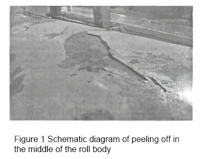
During use, back-up rolls mainly experience two types of failures: spalling of the roll body and spalling at the roll side, known as “shoulder drop.” These failure modes often result in a significant reduction in the effective usable diameter of the back-up roll. As shown in Figure 1, this roll was used as the lower back-up roll in the F2 stand. Spalling appeared in the middle of the roll body in a “cat’s tongue” shape, with cracks propagating circumferentially along the roll surface toward the roll end and radially through the entire working layer. The affected area covered two-thirds of the circumferential surface, with spalling cracks extending to the bonding layer, damaging the hardened layer. This severe defect renders the roll unusable, leading to scrapping, which drastically reduces the effective service life of the roll and increases costs.
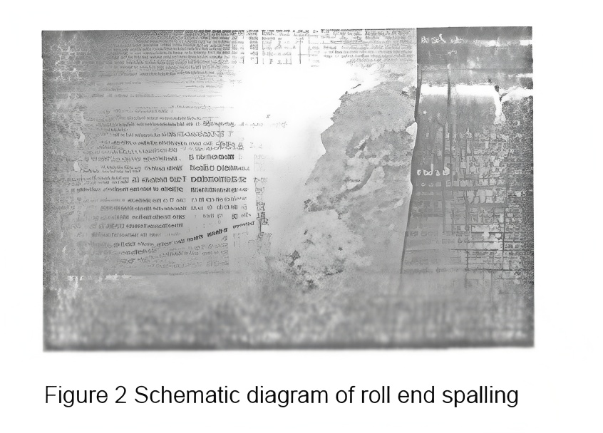
Another form of failure is spalling at the roll side edge, as shown in Figure 2. Although smaller in scale compared to Figure 1, this type of spalling occurs more frequently. It typically appears at the roll end (usually on the operating side). The roll in Figure 2 was used as the upper back-up roll in the F6 stand.
3 Research and Analysis of Back-up Roll Failure Modes
3.1 Basic Parameters
The material of the back-up rolls used in the plant is 75Cr2Mn2NiMo. Its chemical composition, mechanical properties, and basic dimensions are shown in Tables 1 to 3.
Table 1: Chemical Composition (%)
| Element | C | Si | Mn | P | S | Cr | Ni | Mo |
|---|---|---|---|---|---|---|---|---|
| Content | 0.6-1.0 | 0.3-0.8 | 1.0-2.5 | ≤0.03 | ≤0.08 | 1.0-2.5 | 0.8-2.0 | 0.2-1.0 |
Table 2: Mechanical Properties
| Item | Tensile Strength (MPa) | Yield Strength (MPa) | Elongation (%) | Young’s Modulus (MPa) |
|---|---|---|---|---|
| Value | ≥800 | ≥600 | ≥1.5 | 210,000 |
Table 3: Basic Dimensions
| Roll Parameters | Max. Roll Diameter (mm) | Min. Roll Diameter (mm) | Roll Length (mm) | Weight (kg) |
|---|---|---|---|---|
| Roughing BUR | 1385 | 1260 | 1429 | 2649 |
| Finishing F1-3 BUR | 1380 | 1260 | 1429 | 4306 |
| Finishing F4-6 BUR | 1380 | 1260 | 1429 | 2331 |
3.2 Effect of Work Hardening on Back-up Roll Spalling
The back-up roll is continuously in rolling contact with high-hardness work rolls or intermediate rolls, subjecting its surface to periodic compressive stress. This cyclic contact stress often induces a work-hardened layer on the roll surface. When the combined stress from work hardening and rolling exceeds the material’s yield limit, microcracks form and propagate, leading to spalling. The critical hardness increase that causes spalling varies with the required hardness of the back-up roll. Generally, for a back-up roll with hardness above HSD 65, a work hardening increase exceeding HSD 3 poses a spalling risk.
3.3 Effect of Wear on Back-up Roll Spalling
Wear on the back-up roll surface is uneven, resulting in a striped distribution of the work-hardened layer. Hardness differences between these stripes lead to varying stress states. Overloading during rolling—such as accidents like work roll spalling, wrapping, jamming, or sliding—as well as scale embedding, acid pickling, or corrosion, increases local shear stress beyond the yield limit. This causes subsurface microcracks at the base of the work-hardened layer, which propagate inward and outward to the roll surface, resulting in spalling.
Before spalling becomes visible, such microcracks are difficult to detect during roll use, and crack propagation is not apparent. If these subsurface microcracks are not identified and removed during grinding, they will rapidly expand upon reuse, reaching the surface and causing spalling.
3.4 Effect of Metallurgical Defects on Back-up Roll Spalling
Metallurgical defects, such as non-metallic inclusions in the working layer of the back-up roll—particularly brittle oxides and silicates with sharp edges—cause stress concentration at these points. After a certain number of cycles, microcracks initiate and propagate along the inclusions and stress direction, ultimately leading to surface layer spalling.
3.5 Influence of Roll Side Chamfer Design on Shoulder Drop
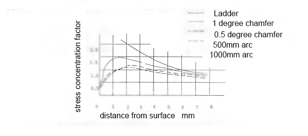
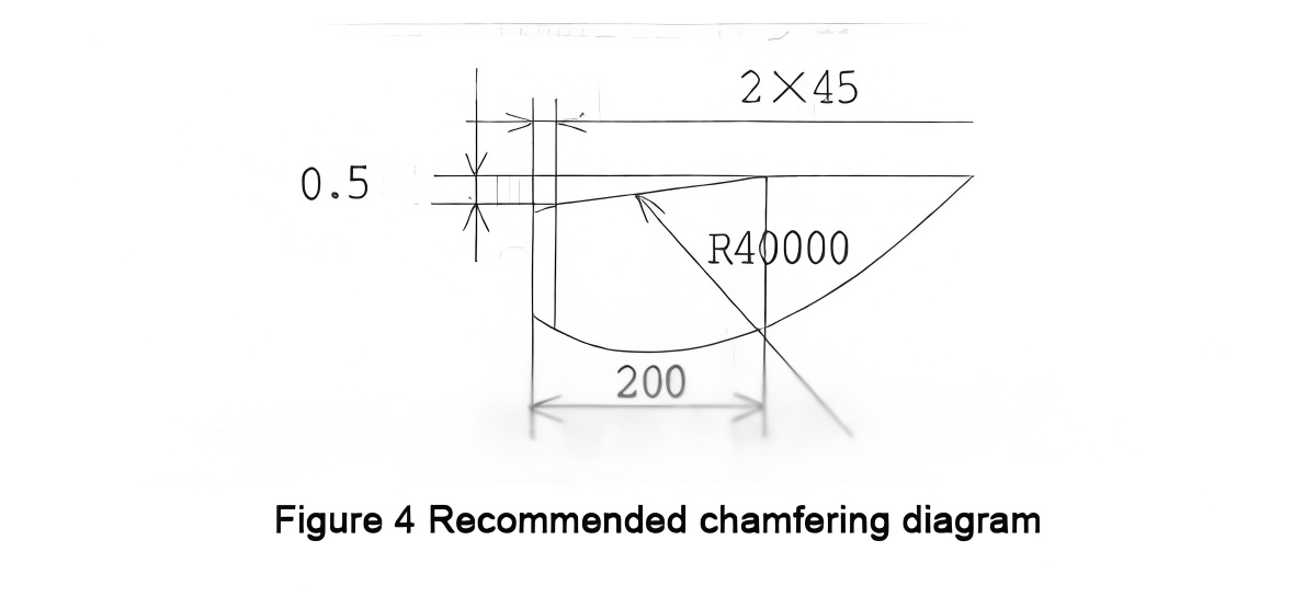
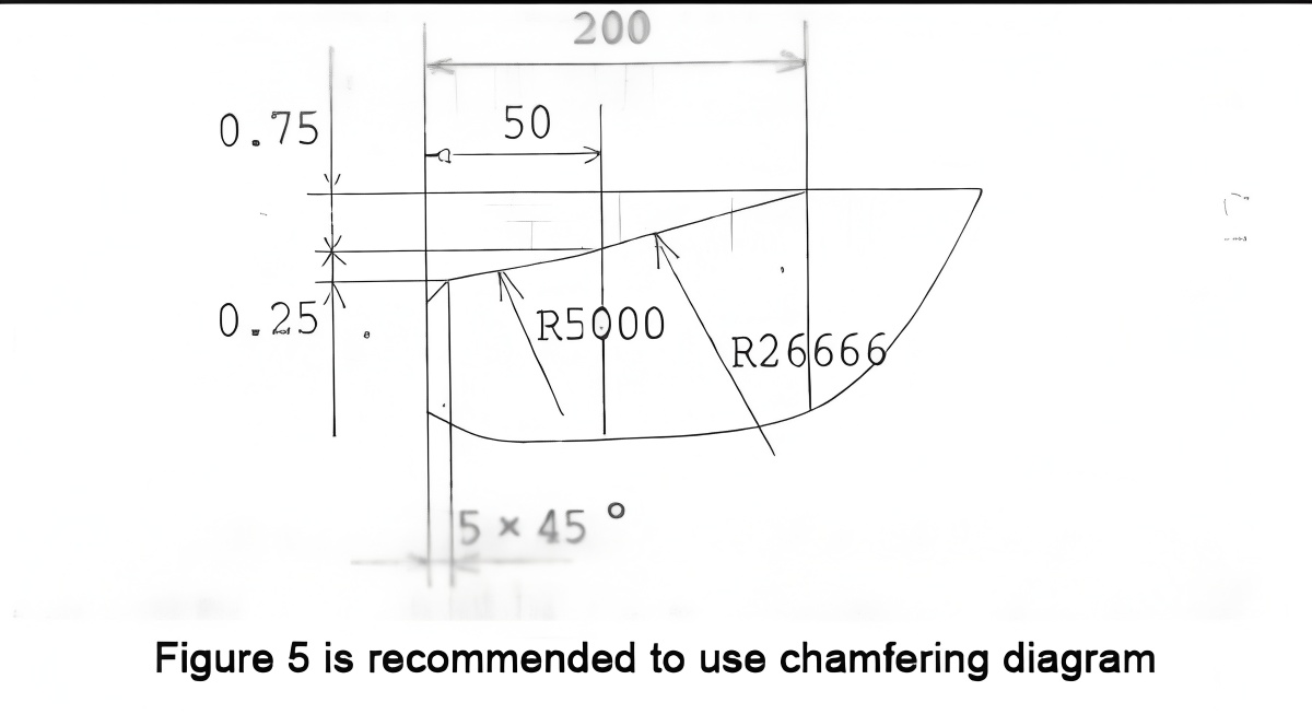
During rolling, uneven wear of back-up rolls and work rolls, combined with positive and negative roll bending forces, results in a concave roll profile with increased contact stress at the roll ends. When this stress exceeds the material’s yield limit, plastic deformation occurs. Repeated alternating deformation generates microcracks, and crack propagation causes shoulder drop. To mitigate or delay this failure, a soft band with lower hardness is often created at the roll end, designed with a conical or arc transition of a certain axial length. The impact of different chamfer designs on stress concentration is shown in Figure 3. Different chamfer types significantly affect stress concentration factors at the chamfered area. When the taper is less than 0.50 radians and exceeds 500 mm, the stress concentration factor becomes negligible. Two recommended chamfer designs are shown in Figures 4 and 5.
4 Processes to Prevent Back-up Roll Failure
4.1 Monitoring Work Hardening
After removal from service, the hardness of the roll surface should be tested and recorded to determine the hardness increase and uniformity. If the hardness increase exceeds HSD 3, the rolling cycle should be appropriately reduced, and the optimal roll change cycle determined through practical adjustment. After grinding, re-test the roll surface hardness to ensure complete removal of the work-hardened layer. The hardness should return to the pre-service level, and values must be documented.
4.2 Fatigue Cracks
Use magnetic particle, penetrant, or ultrasonic testing to perform non-destructive inspection of surface and subsurface microcracks. Ensure fatigue cracks and subsurface cracks are entirely removed by increasing the grinding depth appropriately. Given the extended in-service period of back-up rolls, the fatigue layer must be completely eliminated during grinding. Through continuous effort and exploration, the post-service grinding depth for the fatigue layer was increased from 20 mm to 25 mm, significantly reducing back-up roll spalling.
4.3 Chamfering at Both Ends of the Roll Body
Applying suitable chamfering or large-radius compound chamfering at both ends of the roll body effectively reduces contact stress at the roll ends, preventing shoulder drop. Strict grinding protocols must be followed for newly installed rolls and during each regrinding to effectively prevent shoulder spalling.
5 Conclusion
Back-up rolls are in prolonged rolling contact with work rolls, leading to contact fatigue cracks on the roll surface. Microcracks propagate and eventually cause roll body spalling. Back-up rolls must exhibit high fatigue yield strength, favorable stress states, and crack growth resistance; excellent wear resistance to delay and reduce concave roll formation; and roll necks with good yield strength, toughness, and fracture resistance.