
Fatigue spalling is one of the most critical failure modes of forged steel cold rolling work rolls. In modern high‑speed tandem cold mills, where strip speed can exceed 1100 m/min and strip widths reach 1220 mm, a single work roll failure can lead to strip breaks, cobbles, roll damage, and significant downtime. This article presents a detailed engineering analysis of fatigue spalling in forged Cr5 cold rolled work rolls, based on an actual case from a 1220 mm cold rolling mill, and provides practical guidance for mill roll selection, inspection, grinding, and operation.
Keywords:
mill roll, cold rolling mill rolls, forged steel work rolls, work roll spalling, rolling mill roll material
1. Background: Fatigue Spalling in Cold Rolling Work Rolls
In cold rolling mills, work rolls are the primary contact elements transmitting rolling force and introducing strip shape and surface quality. For high‑hardness forged steel work rolls (typically 94–98 HSD for Cr5 grades), the most common end‑of‑life mode is not gradual wear but fatigue spalling of the hardened working layer. Industry statistics and roll shop records from multiple mills indicate that:
- Fatigue spalling accounts for more than 50% of normal work roll failures in cold rolling.
- Spalling can initiate from surface cracks, sub‑surface material defects, or high contact stress concentrations.
- The resulting fragments may cause strip breaks, cobbles, and secondary damage to backup rolls and mill equipment.
For mills and mill roll manufacturers, understanding the initiation, propagation, and final fracture behavior of these fatigue cracks is essential for optimizing rolling mill roll material, roll shop procedures, and online inspection strategies.
2. Case Overview: Spalling of a Forged Cr5 Cold Rolled Work Roll
2.1 Roll Design and Specification
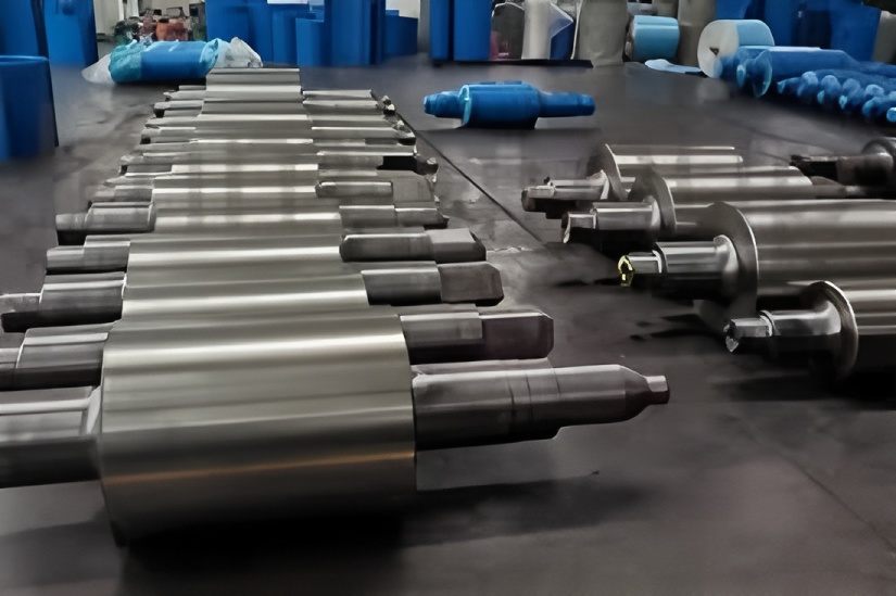
The failed roll was a forged steel cold mill work roll used in the 3# stand of a 1220 mm tandem cold rolling mill. The basic design parameters were:
| Parameter | Specification | Notes |
|---|---|---|
| Roll diameter (new) | Φ535 mm | Work roll barrel diameter as installed new |
| Barrel length | 1219.2 mm | Nominal strip width 1220 mm |
| Total roll length | 3523.35 mm | Including necks and journals |
| Material grade | Cr5 forged steel | High‑carbon, high‑chromium roll steel |
| Working layer hardness (quenched) | 94–98 HSD | Shore D; typical for cold mill rolls |
| Hardened layer depth | ≥ 32.5 mm | Measured from barrel surface |
| Scrap hardness | ≥ 90 HSD | Below this, roll to be scrapped |
At the time of failure, the actual barrel diameter had been ground down to Φ485.9 mm, which means approximately 49 mm of diameter (≈ 24.5 mm per side) had already been removed during previous campaigns and regrinds. The remaining working layer was therefore approaching the hardened layer transition region.
2.2 Mill Operating Conditions and Incident Description
The incident occurred during stable operation of the 1220 mm tandem cold rolling mill at a line speed of 1100 m/min. During rolling:
- A strip break alarm was triggered at stands 4# and 5#.
- After emergency stop, inspection revealed serious cobble entry at stand 3#.
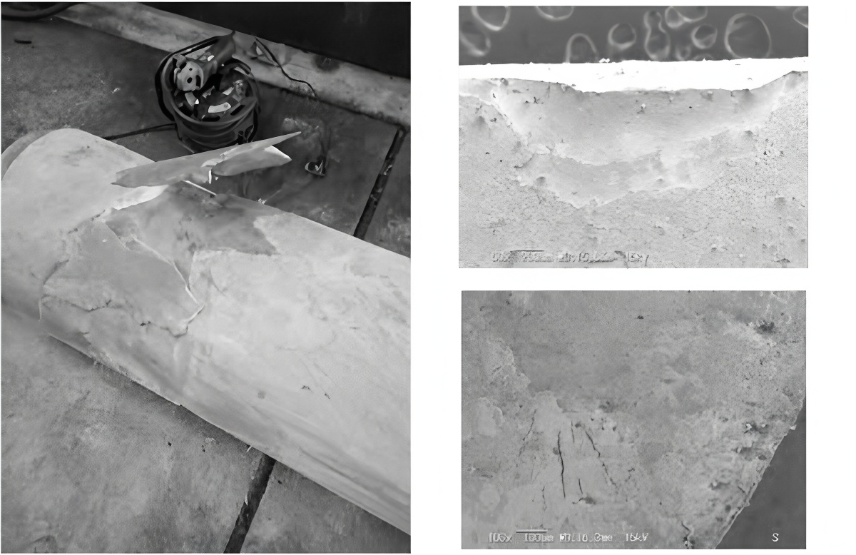
- The lower work roll at stand 3# showed large‑area spalling of the barrel surface, with:
- Spalling depth of approximately 20 mm in the main damaged area.
- Obvious indentations and cracks in and around the spalled zone.
- The lower backup roll edge showed visible crushing damage caused by the cobbled strip and detached roll fragments.
The overall failed roll surface exhibited a characteristic fatigue spalling pattern, which was further investigated by macroscopic inspection, hardness profiling, ultrasonic testing, and metallographic/SEM analysis.
3. Morphological Features of the Spalling Failure
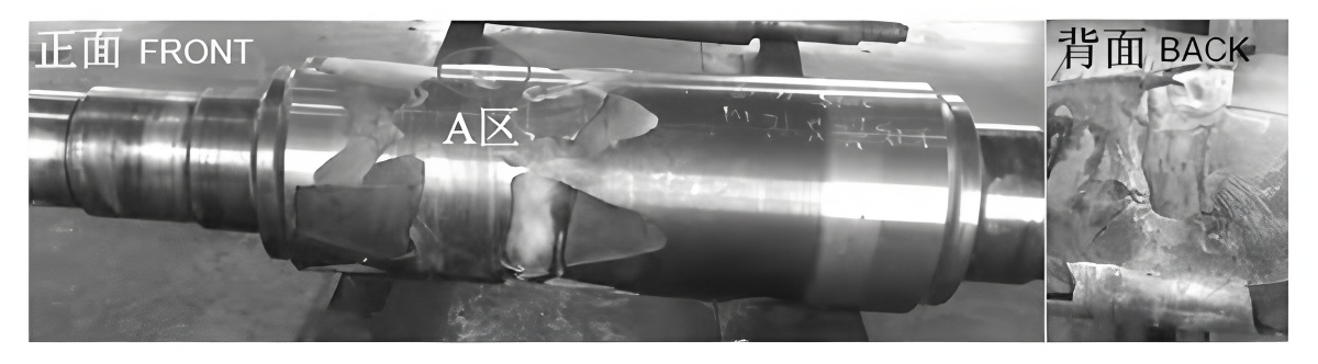
3.1 “Bridge” Shaped Spalling Zone
The most notable macroscopic feature was a “bridge” spalling morphology. Two large spalled segments on the barrel were connected by a narrow non‑spalled region (marked as Area A). From this area, visible fatigue propagation bands could be observed rotating around the roll surface.
These fatigue bands:
- Extended circumferentially from Area A in a clockwise direction (viewed from the drive side).
- Formed one or more continuous loops around the barrel before final spalling occurred.
- Locally appeared bright due to friction polishing, or dull due to surface oxidation, depending on local contact and lubrication conditions.
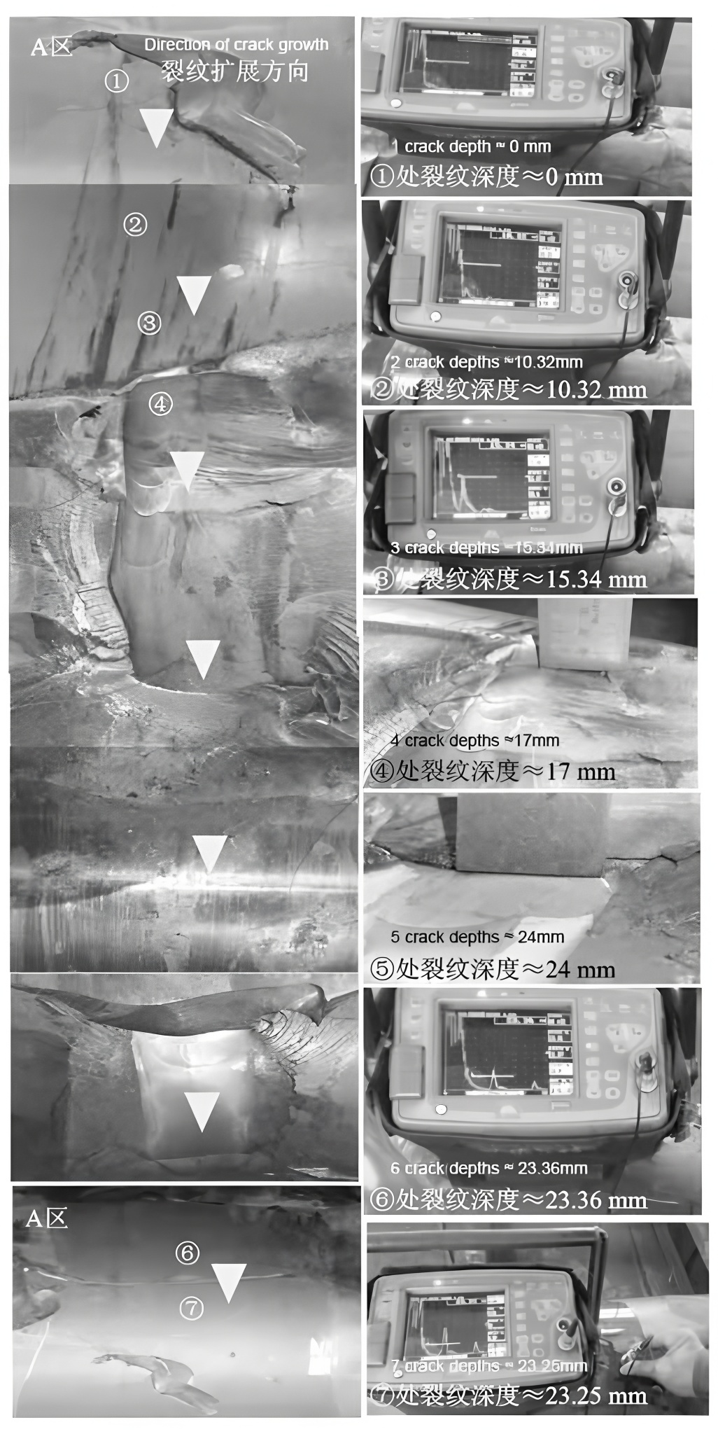
Ultrasonic inspection of the roll confirmed that a circumferential crack had developed along the barrel, originating in Zone A. In front of the fully spalled area, the “front” spalling zone had not yet completely detached but already contained sub‑surface cavities and voids due to ongoing fatigue crack growth.
3.2 Crack Propagation Direction Relative to Roll Rotation
Careful observation of the fatigue marks and the orientation of the main crack demonstrated that:
- The primary fatigue crack initiated at the surface in Zone A.
- It propagated inward into the roll with an angle of approximately 20°–30° to the barrel surface.
- The main crack direction was opposite to the roll’s rotation direction, a typical feature of contact fatigue under rolling contact conditions.
4. Hardness Distribution and Working Layer Integrity
To understand the position of the crack relative to the hardened layer, hardness tests were conducted on both the intact barrel surface and within the spalled region. Measurements were taken at various depths from the original surface.
The key findings were:
- In the non‑spalled barrel areas, the surface hardness remained at 92–93 HSD, only slightly below the original specification (94–98 HSD) and above the scrap threshold (≥ 90 HSD).
- In the spalled region, at a depth of approximately 24 mm below the original surface, the hardness decreased to about 84 HSD.
- This depth corresponds to the soft–hard transition zone between the quenched working layer and the tougher roll core.
| Depth from surface (mm) | Measured hardness (HSD) | Zone |
|---|---|---|
| 0–5 | 92–93 | Working layer (surface) |
| 10–20 | 88–91 | Mid hardened layer |
| 24 | ≈ 84 | Soft–hard transition zone (spalling depth) |
| ≥ 29–32.5 | Further decrease | Core material (tougher, lower hardness) |
This hardness distribution confirms that the fatigue crack propagated until it reached the soft–hard interface, where the change in mechanical properties forced the crack path to turn circumferentially.
5. Origin and Propagation Mechanism of the Spalling
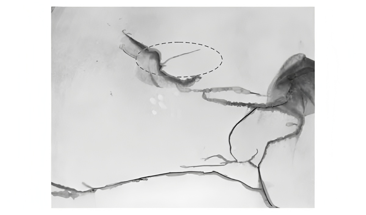
5.1 Surface Crack as the True Origin (Zone A)
Detailed inspection of zone A using dye penetrant testing (PT) revealed a distinct axial surface crack aligned with the observed surface fatigue band. This surface crack was identified as the origin of the entire fatigue spalling event.
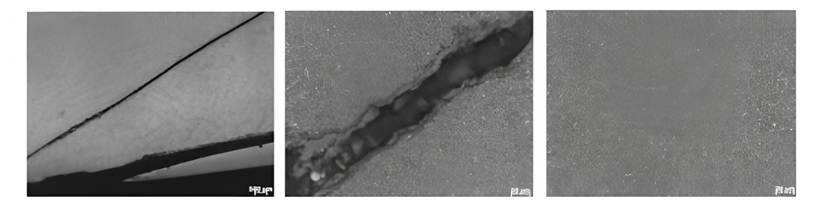
Metallographic examination and scanning electron microscopy (SEM) of the crack region (see Figures below) showed:
- A typical fatigue fracture morphology at the crack origin and propagation zone.
- No significant metallurgical defects such as non‑metallic inclusion clusters, carbide networks, or casting shrinkage in the vicinity of the crack.
- Local evidence of secondary tempering (slight softening) on both sides of the crack, indicating a previous localized thermal shock event.
These observations collectively support the conclusion that the roll material itself (Cr5 forged steel) met the metallurgical requirements, and that the crack initiation was primarily due to operational or maintenance‑related factors rather than intrinsic material defects.
5.2 Role of Local Thermal Shock and Inadequate Grinding
The slight secondary tempering zone along the crack suggests that the roll surface in Zone A had previously experienced local overheating, for example due to:
- A prior cobble or strip break causing frictional heating.
- Severe slipping between strip and roll (insufficient lubrication, mis‑threading).
- Grinding burns or improper cooling during roll grinding.
If the heat‑affected zone is not completely removed by sufficient grinding depth, a micro‑crack may remain at the surface. Under subsequent rolling loads, this micro‑crack can act as a high‑stress concentration site and develop into a progressive fatigue crack. This mechanism is consistent with:
- The presence of a small axial surface crack at Zone A.
- The absence of metallurgical defects elsewhere along the crack path.
- The documented occurrence of a crack alarm during the second coil in the previous campaign.
6. Metallographic and Fractographic Analysis
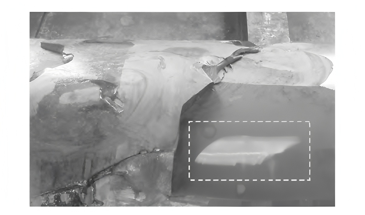
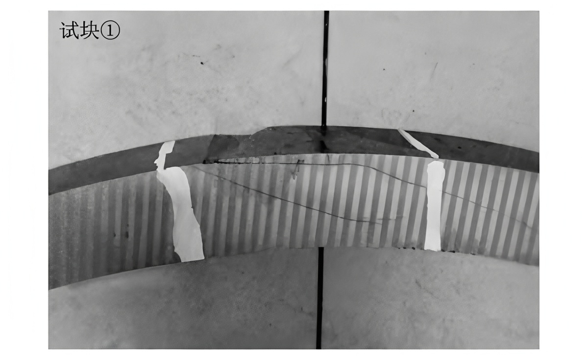
6.1 Sectioning of the Spalled Block
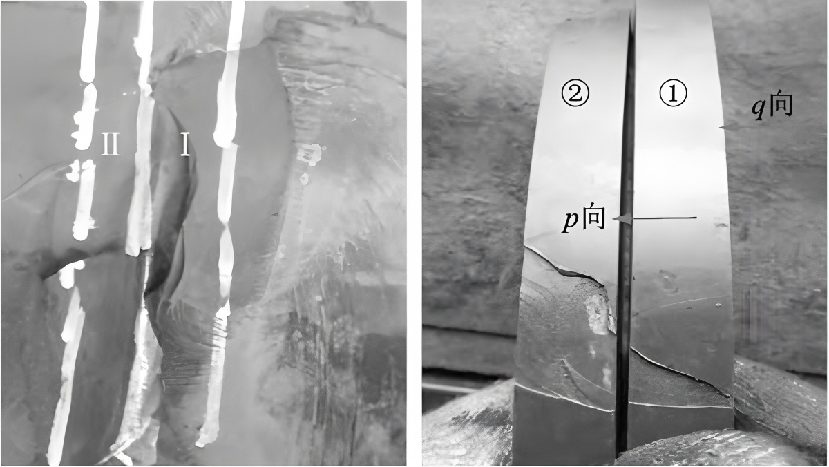
To characterize the internal crack shape and crack path, a representative spalled block was removed and subjected to high‑temperature tempering to relieve residual stresses before sectioning. After tempering:
- Two fatigue propagation bands (Band I and Band II) could be clearly identified, both originating at Zone A.
- Band II was linked to the main circumferential propagation track visible on the roll surface.
Wire‑cutting was then performed along the planned paths to obtain smaller test specimens for detailed metallographic observation.
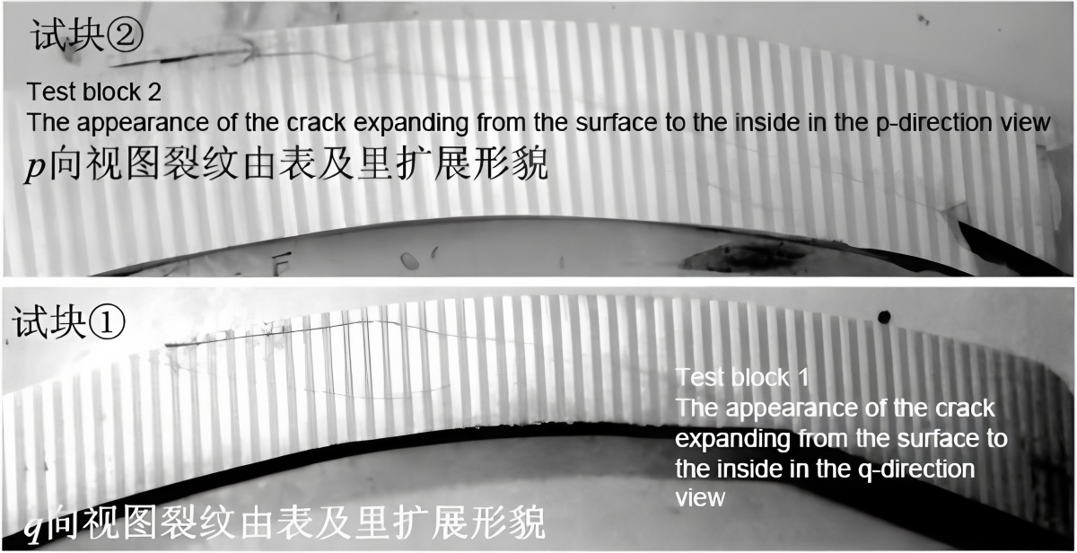
6.2 Crack Path and Deviation at the Transition Zone
Cross‑sectional analysis of the test blocks revealed that:
- The fatigue crack initially propagated inward at an angle of roughly 20°–30° relative to the barrel surface.
- Upon approaching the soft–hard transition interface (around 29 mm depth), the crack path deviated and turned to propagate circumferentially along this interface.
- This resulted in the two observed bands (I and II) which eventually coalesced with the main circumferential crack.

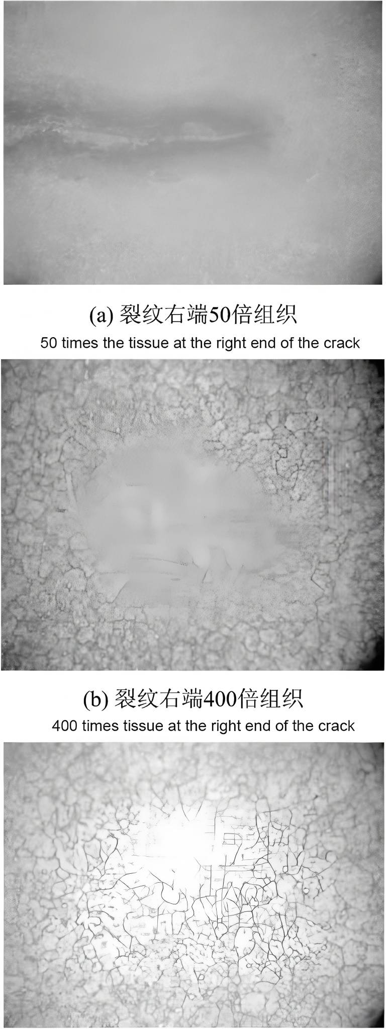
Metallographic observation along the entire crack route showed that:
- The microstructure on both sides of the crack consisted mainly of tempered martensite with granular carbides, which is typical for Cr5 forged work rolls after quenching and tempering.
- There was no observable carbide banding, segregation, or networked carbides that could explain preferential cracking.
- There were no abnormal concentrations of non‑metallic inclusions or other casting‑related defects along the crack path.
These results again confirm that the root cause was not metallurgical quality of the roll, but service‑induced surface damage and subsequent fatigue under rolling contact.
7. Discussion: Comprehensive Failure Mechanism
Combining ultrasonic results, hardness profiling, macroscopic morphology, and metallographic analysis, the failure process can be summarized as follows:
- Initial surface damage occurred in Zone A, most likely due to a prior cobble, local overheating, or grinding burn, leading to the formation of a micro‑crack at the surface.
- This micro‑crack survived subsequent regrinding due to insufficient grinding depth in the affected zone.
- Upon reinstallation, the roll entered service on the 1220 mm cold rolling mill at high speed (1100 m/min). Under cyclic rolling contact, the pre‑existing surface crack experienced high contact stress and started to propagate inward.
- As the crack approached the soft–hard transition zone, where hardness decreases and toughness increases, the crack path deviated to follow this interface, forming one or more circumferential fatigue bands.
- When the crack eventually closed the loop around the barrel, the roll’s structural integrity was severely compromised. Under the high rolling load, a sudden large‑area spalling event occurred, leading to detachment of a thick fragment of the working layer (~20 mm deep).
- The detached fragment and sudden surface discontinuity caused strip break and cobbling at stand 3#, which then propagated downstream and triggered alarms in stands 4# and 5#.
- The cobble and spalled pieces also damaged the backup roll edge, leading to additional repair requirements and extended mill downtime.
Importantly, review of roll shop records showed that:
- Only eddy current testing was performed before the last installation.
- No obvious surface defect was detected at that time.
- However, a crack alarm had already been triggered during the second coil rolled in that campaign.
Since eddy current testing has limited sensitivity for very small surface cracks and near‑surface sub‑surface defects, it is likely that a small crack remained undetected, and continued to grow during operation until catastrophic failure.
8. Practical Guidance for Mill Operators and Roll Shops
8.1 Reduce Mill Incidents and Thermal Shocks
Since the initiating defect in this case was most likely caused by a mill incident (cobble or local overheating), reducing abnormal operating events is the first line of defense. Recommended actions include:
- Strengthen threading and tail‑out control in tandem cold mills to reduce cobble probability.
- Ensure stable lubrication and cooling to avoid hot spots and local thermal shocks on the work roll surface.
- Monitor roll strip slippage and unusual torque spikes indicating loss of friction control.
- Use online surface inspection systems where available to detect early strip or roll surface abnormalities.
8.2 Optimize Grinding Practices and Burn Control
Roll grinding is critical for removing damaged surface layers and restoring optimal geometry. For forged steel work rolls in cold mills:
- Always remove sufficient material from areas that have experienced cobble contact or strip break. The exact depth should be based on experience and inspection (often ≥ 1.0–1.5 mm or more depending on severity).
- Avoid grinding burns by controlling:
- Wheel speed and feed rate.
- Coolant flow and distribution.
- Proper dressing of the grinding wheel.
- Use burn‑detecting fluids or thermal imaging when available to spot overheated areas immediately after grinding.
- Record and track local spot grinding events so that future inspections can focus on these regions.
8.3 Enhance Non‑Destructive Testing (NDT) Strategy
Relying solely on eddy current testing is not sufficient for detecting all critical cracks in cold mill work rolls. A more robust inspection strategy should combine:
- Eddy current testing (ECT) for detecting surface and near‑surface discontinuities, but recognizing its limitations on very fine or closed cracks.
- Surface wave ultrasonic testing (SWUT) to improve sensitivity to small surface cracks and sub‑surface defects close to the barrel surface.
- Conventional ultrasonic testing (UT) in the radial direction for deeper internal defects and for monitoring the integrity of the hardened layer and core.
Integrating surface wave methods with eddy current testing can substantially improve the reliability of defect detection before roll installation, thereby preventing the kind of undetected crack growth observed in this case.
9. Reference Data for Forged Steel Cold Mill Work Rolls
For mill roll specialists, roll shops, and steel producers, the following typical data for forged Cr5 cold mill rolls can be used as a reference when specifying rolling mill rolls and planning roll campaigns.
| Item | Typical range | Remarks |
|---|---|---|
| Material | Cr5 forged steel | High C‑Cr roll steel for cold rolling |
| Surface hardness | 94–98 HSD | Measured on barrel surface |
| Hardened layer depth | ≥ 30–35 mm | Depending on roll size and heat treatment |
| Core hardness | 70–80 HSD | Higher toughness to resist fracture |
| Recommended scrap hardness | ≥ 88–90 HSD | Below this, remove from cold mill use |
| Typical strip speed | up to 1200 m/min | Depending on mill design |
| Typical mill type | 4‑high, 5‑stand tandem cold mill | With backup rolls and bending |
When selecting steel mill rolls or comparing suppliers (for example, forged steel work roll exporters in different regions), attention should be paid not only to nominal hardness values but also to:
- Uniformity and depth of the hardened layer.
- Low segregation and minimal carbide banding.
- Controlled inclusion content and cleanliness.
- Documented performance in similar mills and strip grades.
10. Summary and Key Recommendations
The analyzed case of fatigue spalling in a forged Cr5 cold rolling work roll demonstrates that:
- Spalling often originates from surface cracks rather than internal material defects.
- These cracks can be triggered by local thermal shocks, cobbles, or grinding burns that are not fully removed during later grinding.
- The fatigue crack typically propagates inward and opposite to roll rotation, then turns to follow the soft–hard transition zone circumferentially.
- Once a circumferential crack loop closes, the roll rapidly loses structural stability, causing large‑area working layer spalling and serious mill incidents.
To effectively prevent similar failures in cold rolling mills using forged steel work rolls, the following combined measures are recommended:
- Reduce mill incidents such as cobbles and strip breaks through better threading control, process stability, and strip quality management.
- Improve roll accident resistance via optimized rolling mill roll material design, appropriate hardness distribution, and robust heat treatment to balance wear resistance and toughness.
- Strengthen roll grinding practices, particularly after incidents, ensuring adequate removal of heat‑affected zones and strict control of grinding burns.
- Implement combined NDT methods before each roll installation, using both surface wave ultrasonic testing and eddy current testing to detect small surface and near‑surface cracks that might otherwise be missed.
By integrating these measures, steel producers and roll shops can significantly extend the service life of cold rolling mill rolls, reduce unexpected roll failures, and improve the overall reliability and productivity of tandem cold mills.