
Analysis of Transverse Cracks in Backup Roll Forgings
Cracking remains a significant challenge affecting forging production development and product quality, representing a key research focus within the forging industry. With advancing materials and process technologies, forging cracks manifest in various forms including dense cracking, longitudinal cracking, and transverse cracking. In 9Cr3 steel production, while longitudinal cracking during forging and upsetting has been substantially improved through process optimization, inclusion control, and enhanced ingot surface quality, transverse cracking persists during forging operations.
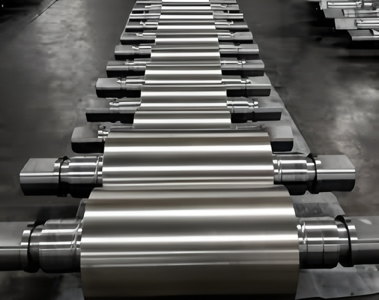
The company’s VC steel ingots are heated using natural gas to temperatures of 1240-1260°C. These ingots typically exceed 50 tons and undergo three forging stages: initial heating for clamping, secondary heating for upsetting and drawing, and final heating for product finishing. Dense transverse cracks typically appear after the second heating stage, particularly prominent on one surface, though not evident during roughing. Figure 1 illustrates the crack pattern following secondary elongation.
Process Review
Transverse cracking generally relates to two primary factors:
Excessive residual elements (Cu, As, etc.) causing area cracking during upsetting/drawing
Spectroscopic analysis of severely cracked areas (Table 1) shows no harmful element exceedances:
Table 1 Spectral Analysis of Severe Crack Areas (mass fraction %)
| P | S | Cu | As | Sb | Sn |
|—|—|—|—|—|
| 0.008 | 0.003 | 0.05 | 0.005 | 0.002 | 0.002 |
Overheating during forging
Historical overheating issues caused severe longitudinal cracking, but no overheating evidence was found in current heating parameters.
Metallurgical Analysis
Non-cracked Areas
1-2mm decarburization depth
Pearlite + minor carbide structure
No inclusions detected (Figure 2)
Severely Cracked Areas
4-5mm decarburization depth
Ferrite structure throughout
No pearlite structure observed (Figure 3)
Sample Analysis
9-10mm deep ferrite structure near cracks
10mm wide ferrite zones
Grain size: 6-10 grade in ferrite regions
Pearlite structure appears beyond 10-12mm depth (Figures 5-8)
Electron Microscopy
Distinct metallic luster differences between pearlite and ferrite regions
Suspected stone-like fracture morphology in pearlite areas
No cleavage structure observed, but passivation signs present (Figures 9-10)
Analysis Conclusions
Transverse crack areas exhibit complete ferrite surface layers versus pearlite in normal areas
Fracture surfaces show overheating characteristics in both structural zones
Scale formation in cracks suggests poor surface structure fluidity during roughing
Subsequent elongation processes force scale into existing cracks
Primary Conclusion
A 10mm deep ferrite layer in transverse crack areas demonstrates poor high-temperature forging performance, causing dense surface cracking. This relates to ingot positioning relative to burners and localized furnace atmosphere conditions. Standardizing ingot placement and regular furnace atmosphere uniformity testing are essential corrective measures.