
The production of high‑quality hot‑rolled strip steel places increasingly stringent demands on backup rolls in hot strip mills. As rolling speeds, strip widths, and total tonnage per campaign rise, backup rolls must provide stable support to work rolls while maintaining predictable wear and profile evolution. This article focuses on the practical
application and management of backup rolls in hot‑rolled strip production, with an emphasis on forged Cr5 backup rolls, wear mechanisms, profile design, inspection, and failure prevention.
From a production perspective, well‑managed backup rolls help:
- Improve strip crown and shape control stability over long rolling campaigns
- Reduce unplanned roll changes and cobbles caused by roll failures
- Extend roll service life to the designed scrap diameter, cutting roll cost per ton
- Support higher reduction schedules and wider strip ranges with fewer quality incidents
The discussion below is based on industrial practice in modern hot‑strip mills (typically 4‑high and 6‑high stands) and provides actionable references for mill metallurgists, roll shop engineers, and rolling technologists.
Role of Backup Rolls in Hot‑Rolled Strip Mills
In a conventional 4‑high or 6‑high hot strip mill, backup rolls (BURs) are large‑diameter rolls that support the smaller work rolls (WRs). Their fundamental functions in hot‑rolled strip production include:
- Providing rigidity and stiffness to the roll stack to minimize work roll deflection
- Helping control strip crown and flatness in combination with WR bending and shifting
- Distributing rolling loads across a larger contact area to reduce local stress
- Storing and releasing elastic deformation during load changes, which affects thickness control
Unlike work rolls, which are frequently changed due to direct contact with the hot strip, backup rolls typically stay in the stand for a much longer campaign. They are subjected to:
- High alternating bending stresses over millions of load cycles
- Rolling contact fatigue at the interface with work rolls
- Thermal cycling due to intermittent contact, cooling water, and stand‑by conditions
Therefore, backup roll materials must combine:
- High toughness and fracture resistance to withstand bending and dynamic loads
- Good wear and spalling resistance against rolling contact fatigue
- Crack growth resistance to delay propagation of subsurface or surface defects
Backup Roll Material and Typical Parameters in Hot‑Strip Mills
Industrial experience in hot‑rolled strip mills shows that a chromium content of around 5% in forged steel backup rolls provides a good balance of hardness, toughness, and rolling contact fatigue resistance. Consequently, most modern hot‑strip mills adopt forged Cr5 backup rolls in finishing stands.
| Parameter | Typical Range / Example (Forged Cr5 BUR) | Technical Note |
|---|---|---|
| Chemical composition (wt%) | C 0.60–0.80, Si 0.40–0.80, Mn 0.60–1.00, Cr 4.5–5.5, Mo 0.4–0.8, Ni ≤1.0 | Typical forged Cr5 backup roll steel, designed for hot strip finishing stands |
| Surface hardness | 60–72 HS (Shore) or ~330–380 HB | Must be uniform over barrel length to avoid local stress concentration |
| Typical barrel diameter | 1,100–1,600 mm (hot strip finishing stands) | Depends on mill type and stand position; later stands often use larger BURs |
| Typical barrel length | 1,800–2,200 mm or more | Must cover maximum strip width plus side over‑hang |
| Designed scrap diameter | Approximately 50–70 mm below original diameter | Determined by strength, neck geometry, and safety factor |
| Service tonnage per campaign | Commonly 200,000–600,000 t per BUR campaign (depending on stand and product mix) | Strongly influenced by wear regime, cooling, and grinding practice |
The exact values vary by mill design, product mix, and roll manufacturer, but the ranges above are representative of many large hot‑strip rolling mills. For steel mill roll manufacturers and users, maintaining chemical and hardness uniformity within these ranges is fundamental to achieving predictable wear and long service life.
Influence of Backup Rolls on Strip Crown and Shape
Strip shape (flatness) and crown are key quality indicators in hot‑rolled strip mills. They are affected by:
- Work roll profile and wear
- Backup roll profile and wear
- Roll bending forces, shifting, and thermal crown
- Stand stiffness and strip tension distribution
Because backup rolls have a much longer replacement cycle than work rolls, their wear has a cumulative effect on the roll stack. Severe or non‑uniform wear on a backup roll can:
- Alter the effective contact zone between BUR and WR
- Change work roll bending response under constant bending force
- Introduce uncontrolled crown or edge waves in the strip
In practice, precise measurement and compensation of backup roll wear are essential for stable shape control in hot‑strip finishing mills, especially in the last stands where tight gauge and shape tolerances are required.
Backup Roll Wear Mechanisms in Hot‑Rolled Strip Production
Backup roll wear follows general tribological principles. From a mechanical and metallurgical perspective, wear can be considered as time‑dependent macro and micro dimensional changes of the roll surface, ultimately reducing the effective barrel diameter and modifying the roll profile.
Main Wear Mechanisms
The main wear mechanisms for backup rolls in hot strip mills include:
- Abrasive wear: Hard oxides and carbides from the work roll surface act as micro‑cutting tools, removing material from the backup roll surface.
- Adhesive wear: Local welding and tearing at micro‑contact spots between BUR and WR, especially under high contact stress and insufficient lubrication/cooling.
- Rolling contact fatigue: Repeated Hertzian contact stresses cause subsurface crack initiation and propagation, leading to spalling.
- Corrosive wear: Cooling water containing oxygen and scale promotes surface oxidation, which weakens the surface layer and accelerates wear when combined with mechanical action.
The actual wear rate is determined by the interaction of:
- Roll material and microstructure (carbide type, distribution, matrix toughness)
- Surface hardness and residual stress state
- Surface roughness and lubrication/cooling conditions
- Inter‑roll contact pressure and relative slip between BUR and WR
- Rolling distance (total tonnage) and strip width distribution
Asymmetric Wear of Upper and Lower Backup Rolls
Extensive industrial measurements consistently show that lower backup rolls wear more severely than upper backup rolls in hot‑strip finishing stands. The main reasons are:
- Cooling water contaminated with oxide scale and mill scale impacts the lower roll more directly.
- Water and scale accumulation tends to be greater in the lower roll region, worsening lubrication and promoting abrasive wear.
- Thermal conditions of lower rolls are usually harsher, with more pronounced temperature fluctuations.
This asymmetry must be taken into account in roll pairing, profile design, and campaign scheduling to maintain symmetric strip shape behavior across the stand.
Operational Measures to Compensate Backup Roll Wear
Before changing the roll profile through grinding, hot strip mills can employ online process strategies to partially compensate for backup roll wear and maintain strip quality. Practical measures include:
1. Rolling Schedule Control
A widely adopted strategy is to match backup roll wear stage with strip type:
- Newly ground backup rolls are used first for wide, thin strip with tight crown and flatness tolerances (e.g., automotive sheet, API line pipe coil).
- As wear progresses, the rolls are gradually shifted to narrower, thicker, and less demanding products, where small deviations in crown and flatness are more tolerable.
This approach maximizes the value of new rolls for high‑value products, while still safely utilizing rolls at later wear stages for lower‑grade products.
2. Reduction Schedule Adjustment
As backup roll diameter decreases due to wear, the effective roll stack stiffness and contact geometry change. To compensate, mills can:
- Reduce the per‑pass reduction in stands with heavily worn backup rolls
- Reallocate reductions to upstream stands with fresher rolls and more margin
- Adjust AGC (automatic gauge control) parameters to reflect updated roll radii
This prevents excessive rolling loads and mitigates the risk of localized over‑loading and strip shape deviation caused by unexpected changes in contact stiffness.
3. Cooling and Thermal Crown Control
Backup roll thermal crown can partially offset mechanical wear or, if not properly controlled, can exacerbate it. A practical technique is to gradually increase edge cooling water as rolls wear, adjusting the temperature profile to:
- Reduce edge thermal expansion when edge wear is high
- Optimize the combination of thermal and mechanical crown to maintain a near‑target profile
- Prevent overcooling that may induce steep thermal gradients and additional stresses
Cooling control should be coordinated with work roll cooling patterns, bending forces, and roll shifting to ensure consistent strip shape response over the roll campaign.
Backup Roll Profile Design and Edge Chamfer Optimization
While online compensation can alleviate some effects of wear, the inherent profile design of the backup roll barrel is the most powerful tool to control wear distribution, contact stress, and strip shape consistency throughout the roll campaign.
Profile Design Based on Industrial Data
Analysis of extensive roll shop and mill data shows that:
- Flat backup roll profiles tend to develop non‑uniform wear patterns, especially in downstream finishing stands, resulting in increased difficulty for shape control.
- Simple sinusoidal crowning can improve initial contact distribution but often leads to uncontrolled shape evolution after several campaigns.
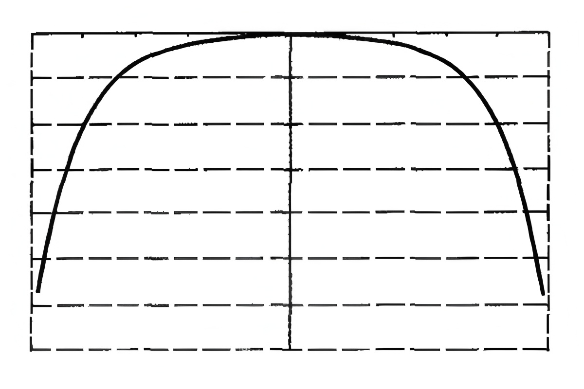
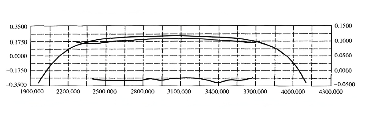
Through repeated production trials and mathematical analysis of wear profiles, it has been found that adopting a “sixth‑power” curve profile on backup rolls significantly improves:
- Wear uniformity across the barrel
- Stability of strip crown during the whole campaign
- Simplification of shape control strategies in finishing stands
A sixth‑power curve type profile (schematically y ∝ x⁶ within the effective barrel length) ensures:
- Gentle change of crown from center to edge, reducing local contact peaks
- More stable contact length between backup and work rolls, even after moderate wear
- Better retention of the designed profile after several grinding and service cycles
From a practical standpoint, this means that the initial design profile is closer to the worn equilibrium profile, minimizing the difference between “new roll” and “mid‑campaign roll” shape behavior. This directly benefits strip flatness and simplifies online control.
Edge Chamfer Design to Reduce Shoulder Spalling
Even with an optimized barrel profile, inadequate edge chamfering can concentrate stress at the roll shoulder, leading to:
- Edge spalling at the contact between backup and work roll
- Premature scrapping of rolls due to shoulder damage
- Serious production incidents when large spalls damage work rolls or strip
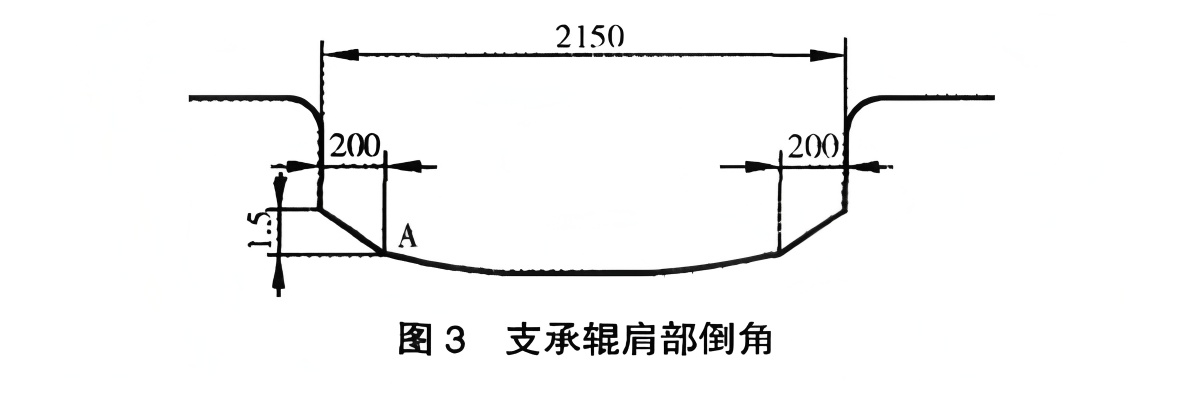
To reduce these risks, the roll edge region is often designed with a compound circular arc chamfer. Typical industrial practice for hot‑strip finishing backup rolls includes:
- Chamfer region length along the barrel: approximately 150–200 mm from each end
- Radial chamfer depth: typically 1–2 mm, depending on mill geometry and load
- Chamfer shape: combination of smooth circular arcs to avoid abrupt curvature changes
The purpose is to create a smooth transition of contact stress from the effective barrel zone to the non‑contact region, minimizing stress concentration in the shoulder fillet zone and thus reducing the probability of fatigue crack initiation.
Backup Roll Management: From Incoming Inspection to Scrap Diameter
Achieving the designed scrap diameter and minimizing unexpected roll failures requires a systematic management approach covering the entire roll life cycle:
- Incoming inspection
- Usage and removal strategy
- Grinding and flaw detection
- Hardness and work hardening control
- Record management and statistical analysis
Incoming Inspection of New Backup Rolls
New backup rolls must undergo comprehensive inspection prior to use, especially for forged steel rolls. Even minor manufacturing defects can grow under cyclic service and lead to catastrophic failures. Recommended tests include:
- Ultrasonic testing (UT) of barrel and necks to detect internal defects (inclusions, shrinkage cavities, segregations).
- Surface hardness mapping along the barrel and around the circumference to verify uniformity and correlation with specifications.
- Dimensional inspection of barrel, necks, and journals, including profile and chamfer geometry.
For any detected internal defect that is structurally acceptable but requires attention, mills should:
- Record the exact position, depth, and orientation of the indication
- Design a special usage plan (for example, limiting maximum rolling load or stand position)
- Monitor the defect evolution during subsequent UT inspections after several campaigns
Normal and Abnormal Roll Removal Management
Backup rolls are removed either at planned intervals or due to abnormal events (e.g., cobbles, sticking, over‑loading). The management strategy differs for each:
Normal Removal
- Allow the roll to cool uniformly to avoid residual thermal stresses before grinding.
- Grind according to predefined depth, based on typical wear rate and hardness increase for that stand/product mix.
- Measure surface hardness along the barrel; if increase exceeds the allowable range, adjust grind depth accordingly.
Abnormal Removal
When rolls are removed due to cobbles, local overheating, or suspected damage, a more conservative procedure is necessary:
- Conduct UT and eddy current (ET) testing on the affected regions.
- Use incremental grinding with repeated inspection to ensure complete removal of cracks.
- Where needed, apply magnetic particle (MT) or dye penetrant (PT) testing on the surface to detect fine cracks.
Although incremental grinding and repeated NDT increase roll shop time, they substantially reduce the risk of putting a roll with hidden fatigue cracks back into service, preventing large‑scale spalling and neck fractures.
Nondestructive Testing and Hardness Monitoring
A modern roll shop handling backup rolls for hot‑strip mills should be equipped with:
- Ultrasonic testing (UT) equipment for internal defect detection and depth sizing
- Eddy current (ET) probes for near‑surface crack detection
- Magnetic particle testing (MT) facilities for surface and near‑surface defect visualization
- Dye penetrant testing (PT) for detecting fine surface cracks in critical zones
- Portable hardness testers to map surface hardness across the barrel
The replacement cycle of backup rolls must be linked with shoulder hardening and barrel hardness increase. A commonly used practical criterion is:
When the roll surface hardness increase exceeds approximately 4 HS (Shore) compared with the original value, the work‑hardened layer must be completely removed by grinding to avoid initiation of rolling contact fatigue cracks.
Roll Record Management and Data‑Driven Optimization
Statistical analysis in many hot‑strip mills shows that a large portion of severe in‑service failures involve backup rolls that had been repaired and reused. Therefore, robust documentation and traceability are essential.
For each backup roll, the roll shop should maintain at least the following data:
- Manufacturing data: material grade, heat number, forging route, heat treatment parameters
- Dimensional data: initial barrel diameter, length, neck sizes, profile and chamfer details
- Service data: stand position, tonnage per campaign, product mix, cooling pattern
- Inspection data: UT/ET/MT/PT reports, hardness maps, crack locations and depths
- Grinding history: grinding depth, remaining diameter, profile adjustments, shoulder treatments
- Incident records: cobbles, over‑loads, thermal shocks, abnormal sound or vibration reports
Regular and fully documented NDT is particularly important for:
- Backup rolls that have experienced spalling or significant localized damage
- Rolls that have been subjected to cobbles or heavy over‑loads
- Rolls approaching small diameters near the designed scrap limit
Continuous improvement of operator skills in UT/ET/MT/PT is also necessary to reduce the likelihood of missed indications and to correctly interpret defect severity, ensuring that only safe rolls are returned to the mill.
Common Backup Roll Failure Modes and Prevention in Hot‑Strip Mills
Despite careful design and management, backup rolls can fail due to several mechanisms. Understanding these modes is crucial for optimizing operation and roll shop practices. Typical failure modes include:
- Barrel (body) spalling
- Edge or shoulder spalling
- Neck fatigue fracture
- Stress‑induced fracture of barrel or neck
Backup Roll Spalling Mechanisms
Spalling generally originates from localized micro‑crack initiation and propagation in the surface or subsurface zone subjected to cyclical rolling contact stress. Common triggering factors are:
- Uneven wear and protruding roll ends
Non‑uniform wear between backup and work rolls can lead to protruding regions at the roll ends. These act as local high spots, significantly increasing edge contact stress. When the local stress exceeds the material’s yield strength repeatedly, plastic deformation accumulates, leading to micro‑crack nucleation and eventual spalling. - Work hardening and rolling contact fatigue
Under repeated Hertzian loading, the surface layer of the backup roll work‑hardens. The superposition of residual stress, rolling contact stress, and tensile bending stress can exceed the fatigue limit, promoting sub‑surface crack growth toward the surface. A marked increase in surface hardness (e.g., more than 4 HS) is a reliable indicator of high work hardening and spalling risk.
If micro‑cracks are not completely removed during grinding, they can propagate during subsequent campaigns. Long service without adequate grinding may produce a characteristic U‑shaped wear profile, concentrating stress near the edges and accelerating local cracking and spalling.
Practical Measures to Prevent Backup Roll Spalling and Fracture
Proven measures to prevent backup roll failures in hot‑rolled strip production include:
- Work Hardening Monitoring and Grinding Control
Measure surface hardness after each campaign. If the increment exceeds ~4 HS compared with original values, increase grinding depth to completely remove the work‑hardened layer, restoring the roll to its specified hardness. - Fatigue Crack Detection and Removal
Use UT, ET, MT, and PT to confirm that fatigue cracks are fully removed after grinding, particularly in edge regions. Incrementally increase grinding depth in zones with persistent indications until all cracks are eliminated within acceptable safety margins. - Optimized Replacement and Grinding Cycle
Determine stand‑specific replacement intervals based on:- Hardness evolution trend (rate of work hardening)
- Accumulated tonnage and rolling load history
- Frequency and severity of prior incidents
Once sufficient data are accumulated, mills can establish predictive grinding schedules that preempt spalling by removing critical damage before it becomes dangerous.
Relation to Other Mill Rolls: Work Rolls, Cold Mill Rolls, and Forged Steel Rolls
Although this article focuses on backup rolls in hot‑rolled strip production, understanding the overall roll system helps optimize roll selection and management. In particular:
- Hot rolling mill work rolls (for finishing stands) are typically smaller‑diameter forged steel rolls with harder surfaces, directly contacting the strip.
- Cold rolling mill rolls (work and backup) operate at lower temperatures but much higher contact pressures, often made from high‑carbon, high‑chromium forged or cast steels, or tungsten carbide composite rolls for extreme wear resistance.
- Forged steel rolls are widely used in both hot and cold mills due to their superior toughness and resistance to catastrophic fracture compared with some cast alternatives.
Many of the principles discussed for hot‑mill backup rolls – such as forged Cr‑Mo steel selection, profile and chamfer design, and NDT‑based grinding management – can be adapted and refined for:
- Cold mill work and backup rolls
- Tungsten carbide roll rings in bar and wire rod mills
- Forged steel work rolls for plate, bar, and section mills
Practical Reference: Key Points for Backup Roll Application and Management
For plant metallurgists and roll shop managers seeking concrete implementation steps, the following checklist summarizes the most important measures to optimize backup roll performance in hot‑rolled strip mills:
| Area | Key Actions | Expected Benefits |
|---|---|---|
| Material selection | Use forged Cr5 backup rolls with controlled composition and heat treatment; specify uniform hardness range. | Higher toughness, improved wear and spalling resistance, reduced catastrophic fracture risk. |
| Profile design | Adopt sixth‑power barrel profile and optimized compound chamfer with 1–2 mm depth over ~200 mm edge length. | More uniform wear, stable strip crown, reduced edge spalling, easier shape control. |
| Cooling and schedule | Control edge cooling and assign new rolls to wide thin strips; shift to narrower/thicker strips as wear progresses. | Better utilization of new rolls for high‑value products; consistent strip quality throughout campaign. |
| Inspection & NDT | Perform UT/ET/MT/PT at incoming, after incidents, and before reuse; map and track all indications. | Early detection of defects, prevention of spalling and fracture incidents, increased roll safety. |
| Hardness & grinding | Monitor hardness; remove work‑hardened layer when ΔHS > ~4; use incremental grinding in damaged zones. | Lower spalling rate, longer effective life per roll, more predictable wear and profile evolution. |
| Data management | Maintain full roll histories (usage, grinding, NDT, incidents) and analyze trends for each stand. | Data‑driven optimization of replacement intervals, profile designs, and cost per rolled ton. |
Conclusion: Improving Backup Roll Utilization for High‑Efficiency Hot‑Strip Production
The performance of backup rolls in hot‑rolled strip production is ultimately evaluated by incident rates, strip quality indicators (crown, shape, thickness control), and cost per rolled ton. As energy conservation and consumption reduction become central goals in steel production, optimizing backup roll application and management is an effective and technically mature pathway to improve mill efficiency.
By combining:
- Appropriate material selection (forged Cr5 backup rolls)
- Scientifically designed profiles and edge chamfers
- Careful control of rolling schedules, reductions, and cooling
- Comprehensive NDT‑based grinding and hardness management
- Rigorous record keeping and data analysis
mills can reliably achieve or approach the intended scrap diameter for backup rolls while minimizing spalling and fracture incidents. The result is smoother production, fewer unplanned stoppages, improved strip quality, and significantly lower roll and downtime costs per ton of hot‑rolled strip.