
Description: The performance and quality of rolling mill rolls directly impact the output and product quality of cold rolling mills, representing a significant production cost factor. After a certain period of use or a specific amount of rolling, the surface develops a fatigue layer and undergoes substantial roughness change, necessitating timely grinding to eliminate hidden risks.
Keywords: rolling mill rolls, rolling mill roll performance
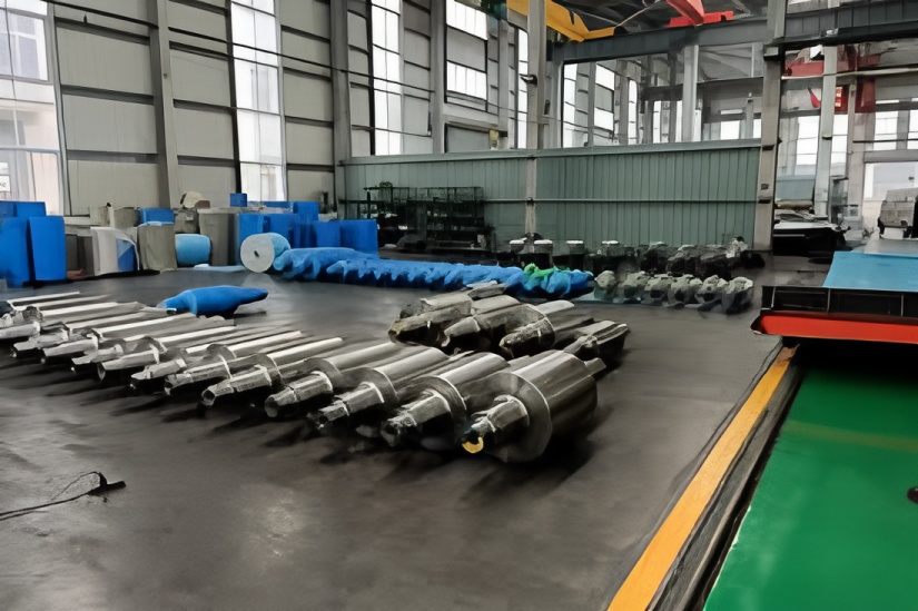
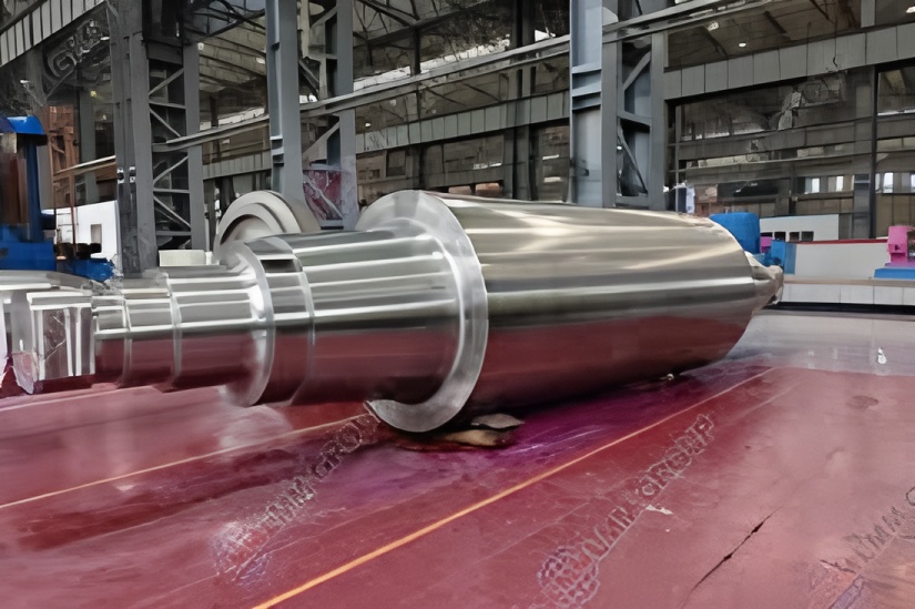
The performance and quality of rolls are crucial in rolling production, directly influencing the output and product quality of cold rolling mills.
Rolls represent a major cost factor in aluminum strip production.
After a certain duration or tonnage of rolling, the surface fatigue layer and roughness change significantly, requiring timely grinding to mitigate risks.
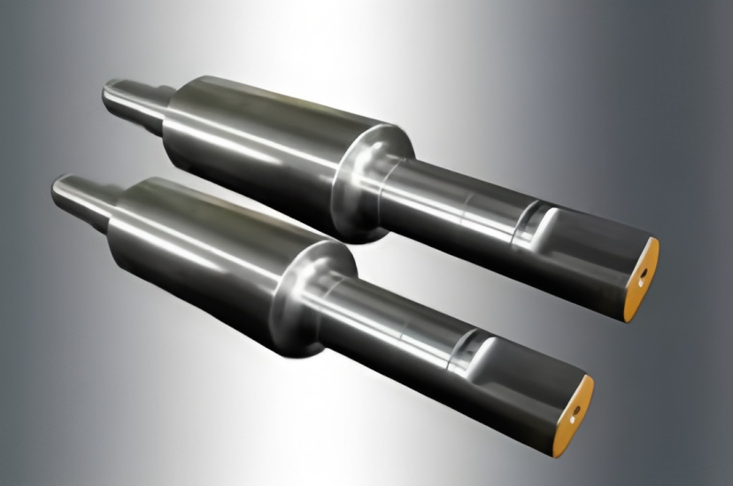
A qualified pair of cold rolls must meet technical requirements for roughness, roundness, cylindricity, diameter tolerance, and convexity, in addition to being free from obvious surface defects.
Basic Components of Mill Roll Records
Number File
Includes roll number, manufacturer, entry date, original hardness, inspection certificate, tolerance, and other original data.
Dynamic Records
Grinding records, rolling pass quantity records, abnormal condition records, image data, etc.
General Requirements for Roll Handling
Move only one roll at a time to prevent contact between rolls.
Use suitable slings at the roll neck for lifting.
Ensure the roll body does not contact any hard surfaces during transport.
Do not weld attachments to the roll for moving purposes.
Electromagnetic cranes are not permitted for moving rolls.
General Requirements for Roll Storage
Place partition pads (wooden wedges, rubber pads) between roll bodies to prevent contact.
Apply anti-rust treatment to the roll neck, sealing area, and roll body.
Store in a stable environment to avoid sudden temperature changes.
Ensure no residual magnetism from storage, support, or equipment.
Cover damaged (spalled) rolls with protective felt, positioning the damage downward. Acoustic emission testing may help assess roll balance.
Grinding must be performed near ambient temperature; avoid rapid cooling.
General Requirements for Roll Usage
Operators should monitor sounds from the rolling mill to ensure safety.
Implement a regular inspection system to prevent parts from falling into the rolled aluminum plate and damaging the roll.
Apply lubrication to prevent bearing dry friction and roll seizure.
Ensure pressure-down procedures remain within design limits.
Common Roll Failures
Abnormal roll surface (aluminum adhesion, orange peel texture, roll marks, soft spots, thermal cracks).
Spalling (caused by roll material issues or contact stress).
Roll neck fracture (due to metal fatigue, material defects, or mill overload).
Roll body fracture (due to metal fatigue, material defects, or mill overload).
Abnormal Roll Surface
Thermal Cracks (Stress Cracks)
Thermal cracks vary from tight, longitudinal micro-cracks to patterns (“crazing,” dry riverbed cracks) of varying density, depending on mill operation and production (hot/cold rolling). Thermal cracks often coincide with soft spots.
Examples of Thermal Cracks on Roll Surface
[Image placeholders]
Roll Spalling
Mechanism
Soft spots (see “Abnormal Roll Surface – Soft Spots”) form thermal cracks.
Stage 1: Re-annealed martensitic steel shrinks, causing uneven stress in soft spots. Stress release excites thermal cracks (stress cracks). As the mill operates, cracks propagate radially and circumferentially, leading to spalling.
Thermal shock (rapid heating/cooling causing spalling) is a severe form of thermal crack, occurring instantaneously due to mill failures (e.g., sticky rolls), which raise roll surface temperature, causing immediate cracking and spalling.
Preventive Measures
Reduce conditions leading to soft spots or thermal shock to minimize thermal crack formation.
Spalling Caused by Roll Surface (Metal Fatigue Cracks, Cracks, Scratches)
Metal Fatigue Patterns on Fracture Surface
Large arrows indicate typical metal fatigue retention marks (beach marks). Small arrows show the direction of fatigue propagation.
Metal fatigue “brittle” cracks appear as annular cracks, sometimes extending to the roll surface.
Characteristics include beach marks and “fan”-shaped fracture lines. Cracks may range from inches to weeks in circumference, with bright (wiped) or dull (oxidized) appearances.
Often accompanied by thermal cracks or mechanical force-induced cracks (roll seals).
Cracks propagate opposite to the roll rotation direction. Radial crack propagation is typical in reversible rolling mills.
Scale Illustration of Metal Fatigue Patterns
[Image placeholders]
Stages of Roll Surface Spalling
1-3: Surface crack initiation (from soft spots, roll marks, scratches, or stress concentrations). Each roll rotation subjects the surface to high tensile/compressive stress cycles, propagating cracks.
4: Cracks propagate radially and circumferentially via metal fatigue, showing gauge and ring fatigue tracks with retention marks and “fan” fracture lines.
5: Cracks continue circulating in the subsurface zone, with continuous ring fatigue tracks showing clear retention marks and “fan” patterns.
6: Surrounding matrix strength declines, leading to spalling. This can occur anytime between stages 4-5, depending on material strength and rolling stress. Final fracture is instantaneous and brittle, originating from the fatigue trajectory.
Preventive Measures
Avoid mill-related roll damage (soft spots, cracks, roll marks, scratches, or stress concentrators).
Shorten rolling cycles and reduce rolling force to prevent surface damage.
Ensure thorough grinding after each cycle.
Inspect rolls with eddy current and ultrasonic testing after grinding to eliminate potential hazards.
Contact Stress (Crushing) Fatigue Spalling
[Image placeholders]
Due to mill load and localized roll flattening at contact points, maximum shear stress (“Hertz stress”) below the surface can initiate multiple cracks. Occurs in two modes:
Instantaneous: Sudden Hertz stress increase from mill faults (e.g., winding, slipping, sudden stops). Stress exceeds roll compressive strength, causing immediate crack formation and propagation.
High-Frequency Metal Fatigue: Common in backup rolls, often without mill incidents. “Brittle” spalling results from long-term subsurface crack initiation, explained by S-N fatigue diagrams. Stress cycles below material strength can still cause cracks if frequency is sufficient.
Preventive Measures
Avoid mill faults (slipping, winding, sticky rolls).
High-Frequency Contact Stress Metal Fatigue
Point loads (e.g., metal debris, weld residue, stress concentrators) can initiate small surface cracks if stress exceeds material compressive strength. Cracks propagate rapidly via fatigue, leading to spalling.
Preventive Measures
Prevent abrasive or solder entry into roll gaps.
Post-grinding inspection with dual-probe ultrasonic and surface wave techniques.
Ensure sufficient grinding to remove or reposition cracks to low-stress zones.
Shorten roll change cycles to reduce stress frequency.
Reduce rolling force to lower shear stress.
Optimize roll profile (work/backup roll convexity) for uniform contact.
Design work roll edges to reduce stress concentration.
Design backup roll edges with rounded corners and appropriate relief (~0.5°) to minimize stress.
Contact Stress Fatigue Spalling
Stress concentration at plate edges, work rolls, and backup rolls can initiate cracks. Repeated stress cycles cause cracks to propagate to the surface, causing “crushed” spalling. Fatigue trajectories may form subsurface, leading to larger spalling.
Backup Roll Spalling
Usually high-frequency fatigue spalling, often with “crushed” appearance. Softer backup rolls show larger spalling. Cracks may develop sub-surface before emerging.
Common at roll body center, edges, or work/backup roll contact points.
Preventive Measures
Post-grinding ultrasonic and surface wave inspection.
Sufficient grinding to remove or reposition cracks.
Shorten roll change cycles.
Reduce rolling force.
Increase backup roll hardness.
Design backup roll edges with rounded corners and relief.
Reduce roll convexity to lower shear stress.
Instantaneous Fracture – Mill Overload
Roll Neck Fracture
Occurs along a 45° transverse shear plane. Single-point initiation with fracture lines across the surface. Mid-fracture shows plastic deformation; no fatigue marks indicate instantaneous failure.
Caused by sudden bending stress exceeding neck material strength.
Preventive Measures
Avoid mill faults.
Eliminate sudden bending stress on roll necks.
Roll Body Fracture
Similar to neck fracture: 45° shear plane, single-point initiation, plastic deformation, no fatigue marks.
Caused by sudden stress exceeding body material strength.
Preventive Measures
Control mill load and operation to avoid abnormal stress concentration.
Influence of Grinder Parameters on Roll Grinding Quality
Modern roll grinders must handle complex roll profiles, stricter tolerances (eccentricity, roundness, circular runout, taper), smaller tolerances, and advanced detection (size, flaws, hardness, roughness). Achieving high precision requires optimal grinder accuracy, grinding wheel selection, coolant, and process parameters.
Grinding Wheel Selection
Aim for short grinding time, minimal wheel wear, and no self-excitation.
Abrasive Selection
Corundum wheels for hardened/non-hardened steel rolls.
Silicon carbide wheels for chilled cast iron, rubber, copper, or granite rolls.
Match abrasive to material: chromium corundum (PA) for alloy steel, zirconia corundum (ZA) for heat-resistant alloy steel, single-crystal corundum (SA) for stainless steel.
Grit Size Selection
Coarse grit (24-60) for rough grinding.
Fine grit (60-100) for fine grinding.
Very fine grit (W64-W14) for precision grinding.
Hardness Selection
Softer wheels for harder roll surfaces.
If wheel wears too fast: increase wheel speed, increase workpiece feed per revolution to 2/3–3/4 wheel width, or reduce roll speed. If ineffective, use a harder wheel.
If wheel loads or burns roll surface: reduce wheel speed, increase roll speed, or use a softer wheel.
Bond Selection
Ceramic bond (A): Chemically stable, water/acid/heat-resistant, low cost, but brittle. Common for most wheels.
Resin bond (S): High strength, elastic, good for high-speed grinding, cutting, grooving. Poor heat resistance.
Rubber bond (X): Elastic, good for polishing. Used for guide wheels, cutting, grooving, polishing. Not for rough grinding.
Metal bond (J): e.g., bronze (Q), for diamond wheels. Good formability, strength, toughness. Poor self-sharpening.
For mirror finishing, use resin bond; for other surfaces, ceramic bond is preferred.
Grinding Coolant Selection
Functions
Cooling
Cleaning
Rust prevention
Common Coolants
Saponification fluid: Good lubricity, poor rust prevention, average cooling, short service life.
Chemical coolant: Good rust prevention and cooling. Often contains sodium nitrite, which is hazardous.
New grinding fluids: Environmentally friendly, odorless, excellent cooling/cleaning, good rust/corrosion prevention. Higher cost.