
Solving the Problem:
How to optimize rolling mill roll usage
Increasing roughing mill production capacity
High-chromium steel rolls were developed in Europe in the early 1980s to replace inferior roll materials like semi-steel rolls, centrifugal cast infinite chilled cast iron (ICDP), or forged steel rolls. This material was subsequently adopted in the roughing stands of most hot strip mills and early thin slab continuous casting/rolling finishing mills.
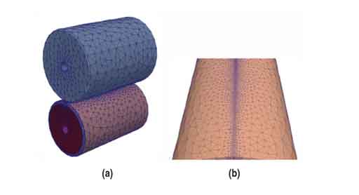
Growing demands for higher output, improved product quality, and enhanced safety in roughing mills drove roll manufacturers to develop new steel grades in the early 1990s, namely semi-high-speed steel. This material saw rapid, widespread adoption, particularly in Western Europe. However, applications like stainless and special steel rolling required further improvements, leading to the development of specialized roughing mill High-Speed Steel (HSS) in the late 1990s. Figure 1 shows this evolution of strip roughing mill work rolls.
The introduction of semi-high-speed steel rolls significantly improved roughing mill work roll life and enabled a shift from standard 7-pass to 5-pass reduction schedules, increasing the capacity of reversible roughing mills, largely due to the superior bite capability of these rolls.
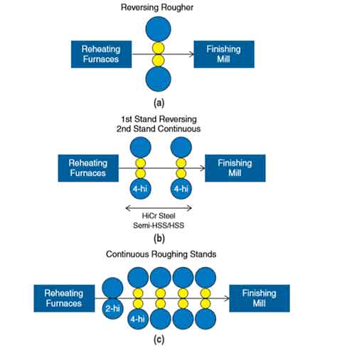
In the late 1980s, high-chromium steel rolls typically achieved rolling cycles of 20,000–40,000 tons in semi-continuous mills and 80,000–100,000 tons in fully continuous mills. Today, using semi-high-speed steel rolls, cycles range from 65,000–120,000 tons for semi-continuous mills, while fully continuous mills can reach 200,000 tons, representing a doubling or tripling of volume per roll pair per cycle.
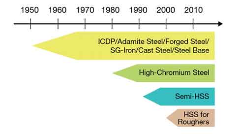
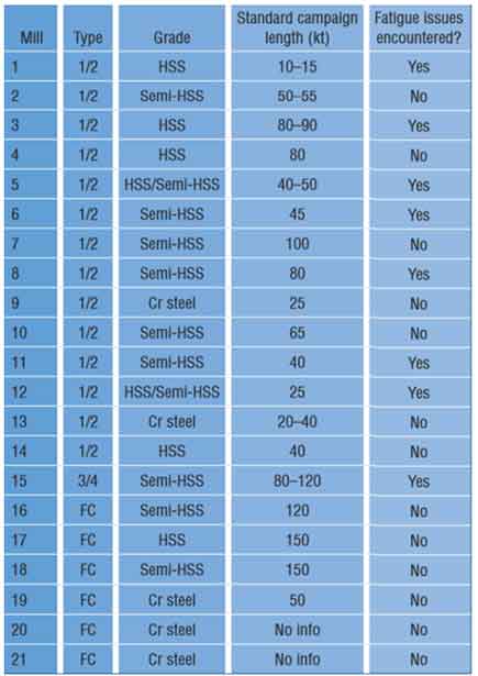
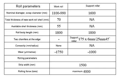
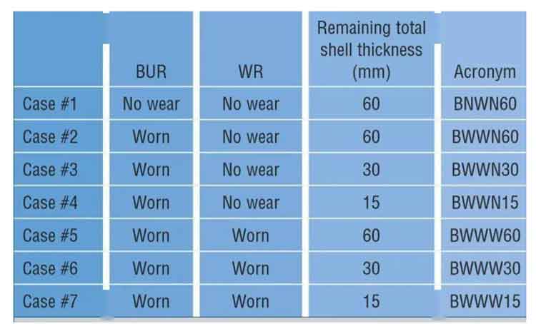
Table 1 illustrates the current status of roll types and rolling volumes per cycle for most European hot strip mills, summarizing data from carbon and stainless steel strip mills (excluding plate/coil mills). It details mill type, roughing mill work roll type, total strip tonnage per standard cycle, and presence of fatigue issues.
The core material of newer generation roughing mill rolls remains largely unchanged, as do the interface properties of the shell. However, with increased rolling loads (longer cycles, 5-pass instead of 7-pass schedules), fatigue has become more prominent. These issues are observed on roughing mill work rolls, sometimes causing premature shell-core interface (bonding zone) failure, primarily in semi-continuous or 3/4 continuous mills, but not yet in fully continuous mills.
In Europe, 8 out of 15 reversible roughing mills face fatigue problems, a number increasing annually. A common solution is increasing the roll scrap diameter, leaving a ≥25mm shell thickness at scrap to prevent bonding zone fatigue.
Fatigue in roughing mills continues to cause premature failure of work and backup rolls. Often, this can be addressed through work roll chamfer, roll body crown curve, proper work roll shell design, or adjusting rolling volume.
To tackle this, HANI developed a specialized modeling tool.
Solving Premature Work Roll and Backup Roll Failure:
Development of a digital tool for predicting work roll and backup roll stress.
The tool is fully parameterized for quick adaptation to various mill configurations. Its purpose is to flexibly suit user sites, incorporating material properties and roll design, and is practical for mill use. It helps describe the current mechanical load on rolls and propose solutions for improved usage.
Required data for work and backup rolls includes:
Roll diameter.
Roll body length.
Chamfer and edge geometry.
Roll body crown/profile.
Wear curve.
Mechanical properties (shell, bonding zone, core).
Work roll shell thickness.
Fatigue resistance (core material).
Required rolling parameters include:
Rolling force.
Slab width (average, min, max).
Rolling cycle.
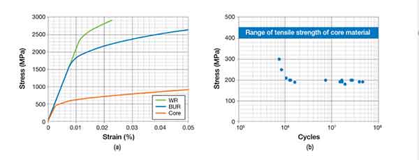
Geometry and rolling parameters are crucial for model accuracy. Material properties, mechanical characteristics, fatigue resistance, and work roll shell thickness are sourced from the roll manufacturer’s database. The model’s mechanical properties are based on experimental measurements of material compressive yield stress, aligned with theoretical work-hardening laws. As crack initiation/propagation laws aren’t modeled, ultimate tensile strength isn’t considered. Manual verification checks if maximum stress aligns with the material’s ultimate strength.
The model also considers core fatigue resistance, the work roll’s weakest part. For safety, bonding zone characteristics are treated as core material in result interpretation.
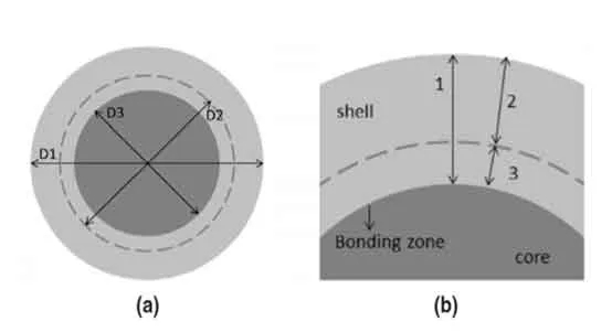
To avoid confusion, here are definitions for roll diameter and shell thickness (see Figure 5):
D1: Outer diameter.
D2: Scrap diameter (performance guaranteed down to this diameter).
D3: Core diameter.
Total Shell Thickness: As-delivered or remaining after grinding.
Usable Shell Thickness: Parameter of interest to users.
Residual Shell Thickness at Scrap Diameter: Thickness below which performance isn’t guaranteed. Standard practice was 15mm, but often increased to ≥30mm to prevent fatigue.
Influence of Shell Thickness and Roll Profile on Stress
Based on industrial data and mill conditions, the influence of shell thickness on work roll surface and bonding zone stress was calculated for several scenarios.
This analysis considered a mill using backup rolls with two straight chamfers. Work roll and backup roll wear at the center reached 1750µm and 1000µm, respectively.
Fatigue damage in the bonding zone was observed when the residual shell thickness reached 30mm (15mm more than the specified 15mm). The initial shell thickness was 70mm, meaning rolls could still be used below 30mm residual thickness. Stress distribution was calculated for three shell conditions:
60mm shell thickness (simulating a used roll, 10mm ground from new).
30mm shell thickness (point where fatigue damage begins).
15mm shell thickness (residual thickness at scrap diameter).
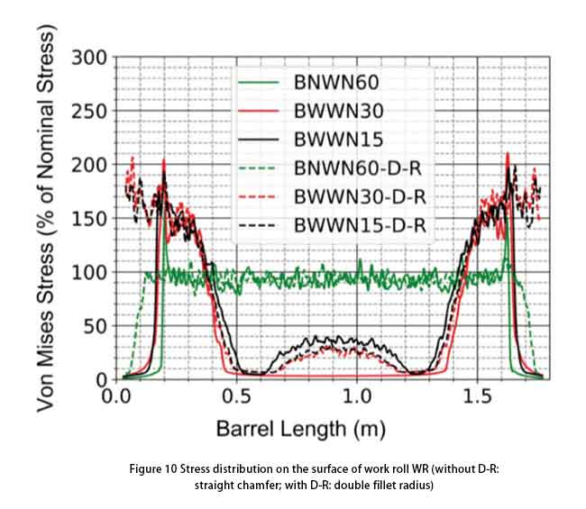
The influence of roll profile was studied under three conditions: unworn straight profile; ground (worn) backup roll (BUR) and work roll (WR); and worn BUR and WR.
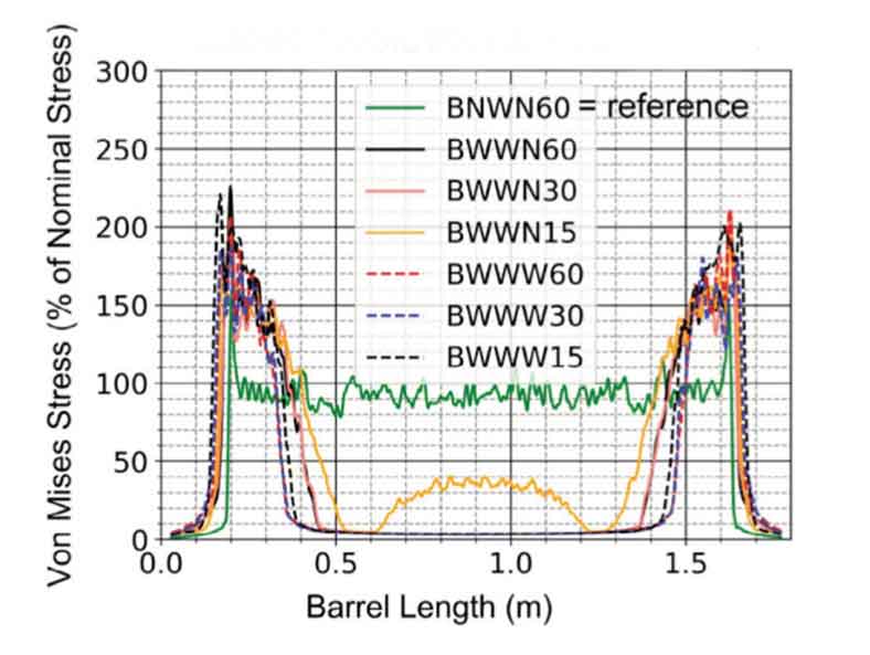
Results show the evolution of Von Mises stress across the roll body width. Using the 60mm shell, ground BUR/WR condition as the 100% reference, stress under other conditions was compared. Key findings:
Maximum stress occurs 175–200mm from the roll edge, corresponding to the end of the backup roll chamfer.
With a worn backup roll, WR-BUR contact is limited to 400mm wide areas on both sides, causing ~220% stress in these zones (vs. 150% in reference).
Work roll shell thickness has limited effect on surface stress.
At 15mm shell thickness (scrap), stress increases at the roll center due to higher bending. This effect is minor and compensated by backup roll wear.
With a worn backup roll, stress at the WR edge increases by 400% vs. reference.
Work roll wear has limited impact (400-500%) compared to backup roll wear.
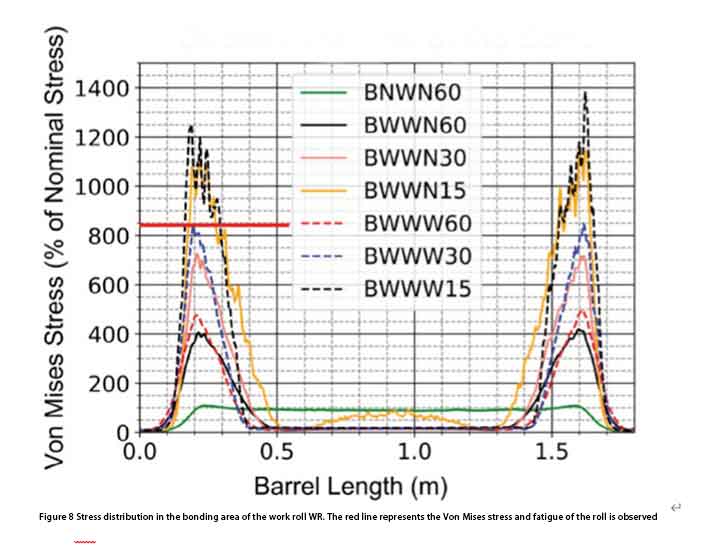
Reducing shell thickness from 60mm to 30mm and 15mm under wear conditions increases bonding zone stress from 500% to 850% and 1200%, respectively.
Since no fatigue is observed via UT when shell thickness remains >30mm, the maximum allowable Von Mises stress in the bonding zone is concluded to be below 850%.
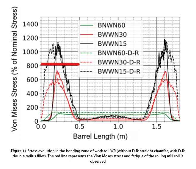
Modifying Backup Roll Chamfer
The backup roll chamfer was modified from straight to a double-radius configuration. Three scenarios were simulated:
Ground BUR/WR, 60mm WR shell.
Ground BUR/WR, 30mm WR shell.
Ground BUR/WR, 15mm WR shell.
The chamfer change had minimal effect on surface stress. However, in the bonding zone at 30mm shell thickness, stress was limited to 600% compared to 750% with the straight chamfer.
Conclusion
The model effectively identifies the location and cause of fatigue damage and the impact of backup roll chamfer geometry on stress. The full study also evaluated maximum allowable wear for work and backup rolls to reach the 15mm residual shell scrap diameter. This comprehensive analysis enables roll manufacturers and users to identify the optimal combination of parameters.