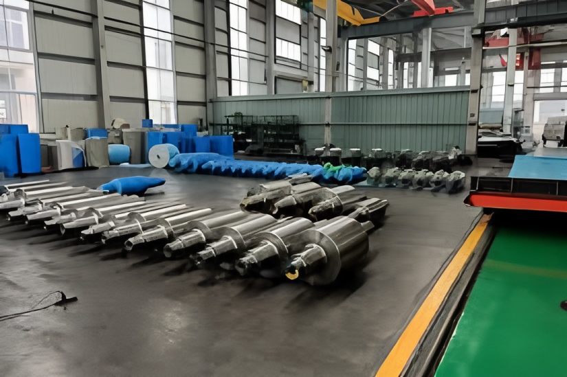
1.1 Pre-Assembly Preparation
(1) Verify dimensions and accuracy of new roll components against equipment drawings. Check groove patterns using templates. Report any discrepancies to relevant departments and maintain records for resolution.
(2) Inspect bearing housings and labyrinth ring assemblies for:
Component fit clearances
Balance cylinder height and functionality
Remove burrs, sharp edges, and rust
Ensure lubrication passages are clear and clean
(3) Clean all bearings and components with diesel or cleaning oil. Apply anti-rust lubricant to machined surfaces. Fill rolling bearings with Lithium Base No. 3 grease.
1.2 Assembly Sequence
(1) Install seals on roll necks
(2) Heat bearing inner rings using induction heater and mount on roll necks
(3) Install spacer rings
(4) Adjust backing plate height in bearing boxes
(5) Gently tap cleaned bearings into housing with copper rod
(6) Install retaining rings
(7) Assemble bearing boxes with bearings onto roll bodies
(8) Install thrust bearings into bearing boxes
(9) Mount bearing retaining rings
(10) Secure locking rings
(11) Install snap rings
(12) Tighten lock nuts
(13) Mount end covers (non-drive end)
(14) Install additional components as required
1.3 Key Precautions
(1) Maximum bearing inner ring heating temperature: 170°C
(2) Maintain original bearing component matching; verify clearance with feeler gauges for reused bearings
(3) Handle new bearings in original packaging until assembly; preserve factory anti-rust coating
(4) Use copper rods for bearing installation – no direct hammer strikes
(5) Maintain clean hands without gloves during greasing
(6) Position assembled rolls at designated locations after inspection
(7) Maintain clean work environment
(8) Ensure proper roll line alignment and elevation during pre-assembly
(9) Verify elastic pad tightness and replace if clearance below 5mm specification
(10) Label pre-assembled rolls with diameter, date, and assembler name
1.4 Roll Processing Quality Standards
(1) Maintain detailed acceptance records
(2) Verify all machining meets drawing specifications
(3) Allowable turning amounts:
Stands 1-4: 10-15mm
Stands 5-9: 10-12mm
Stands 10-14: 8-10mm
(4) Diameter tolerance:Stands 1-4: ≤0.60mm between rolls
Stands 5-9: ≤0.50mm between rolls
Stands 10-14: ≤0.30mm between backup rolls
(5) Process matching rolls simultaneously; max groove misalignment: 0.2mm
(6) Mark defects (blisters, etc.) with paint
(7) Align center frame supports with roll centerline
(8) Eliminate visible old groove marks and water cracks
1.5 Roll Diameter Specifications
Stands 1-4: Max Ø610mm, Min Ø520mm
Stands 5-9: Max Ø495mm, Min Ø420mm
Stands 10-14: Max Ø380mm, Min Ø330mm
Process according to most worn groove. Reject and document any non-conforming products, reporting to supervisors immediately.

